11
NOTE: Setting the index line to
1
/4" on the ring means the cutting edge of the
bit is exposed
1
/4
" below the base.
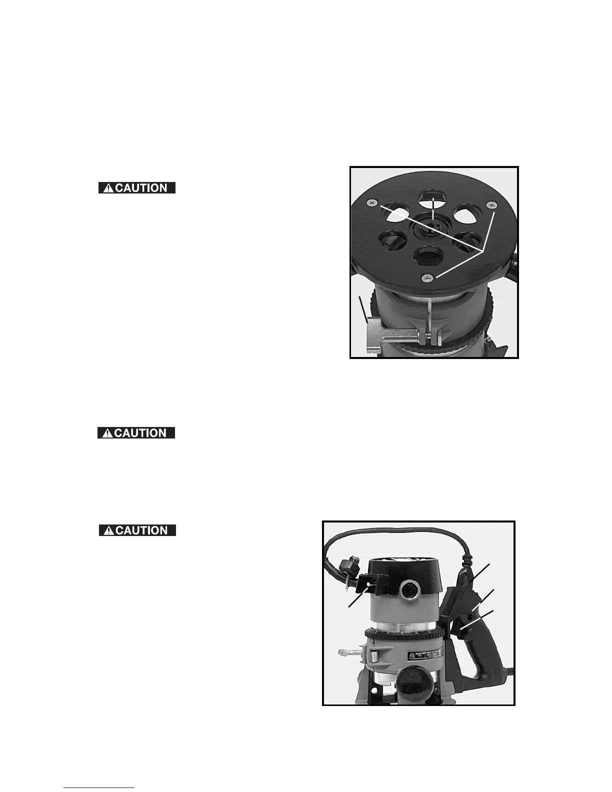
ADJUSTING SUB-BASE ALIGNMENT
Applications using a templet guide require the bit to be centered in the guide.
This, in turn, requires the center hole in the sub-base to be in line with the
collet of the motor unit. Your model has an adjustable sub-base which has
been aligned at the factory. If the sub-base has been removed and/or
readjustment is required, use the following procedure:
Be sure that the power
switch is in the “OFF” position and that the
machine is disconnected from the power
source to avoid accidental starting of the
motor which could result in personal injury.
1. Loosen the sub-base mounting screws
just enough to allow the sub-base to move
on the base.
2. Loosen the clamp screw (C) Fig. 6, and
adjust the motor so that the collet nut
engages the center hole in the sub-base.
Allow the sub-base to center itself on the
collet nut. Tighten the clamp screw.
3. Tighten sub-base mounting screws
securely.
CONNECTING TO THE POWER SOURCE
Before connecting router to power source, ALWAYS MAKE
SURE THAT THE SWITCH IS IN THE “OFF” POSITION.
Also check to see that the power circuit is the same as that shown on
specification plate of the router.
STARTING AND STOPPING THE MOTOR
Before starting the
router, clear the bit of the workpiece
and foreign objects. Also keep a firm
grip on the router to resist starting
torque.
When using the 691, which is
equipped with a switch-in-handle
(Fig. 8), check to see that the motor
unit power cord (A) is plugged into
the handle, and that the switch (B) on
the motor is set to the ON position.
The starting and stopping of the
motor is then controlled by pressing
and releasing the trigger switch (C)
Fig. 8 in the handle of the base.
Fig. 6
A
B
C
Fig. 8
A
C
B
D