14
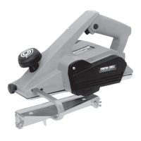
SIDE RAILS
Two knobs (A) Fig. 12 are provided for
controlling the movement of the side
rails, above or below the pad. For
manual instruction purposes, the right
knob is on the same side of the motor
frame as the sander handle. The right
side rail is controlled by this knob. To
lower the right side rail, turn the right
control knob toward the front of the
machine. To raise the right side rail,
turn the right control knob toward the
rear of the machine. To lower the left
side rail, turn the left control knob
toward the rear of the machine. To raise the left side rail, turn the left control
knob toward the front of the machine.
The distance of the rails above and below the pad edge determines the depth
of cut. For most applications, satisfactory operation will result when one side
rail is adjusted so it is 1/32" above the pad edge, and the other rail 1/32"
below the pad edge (see Fig. 12). For removing very thin coats of paint, make
the depth of cut smaller by moving the rail above the pad downward. Use a
piece of scrap lumber to try several positions until you find the height best
suited for the job. Do not change the position of the rail that is 1/32" below the
pad edge.
USING THE PAINT REMOVER
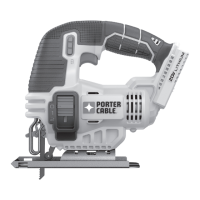
SPOT SANDING
To sand small areas, start the motor and place the button-head guide screws
against the edge of the clapboard above the sanding area. Lower the
abrasive disc on the clapboard and move the machine back and forth from
left to right until the paint has been removed (Fig. 13). To sand close to the
edge of the board above, tilt the tool forward.
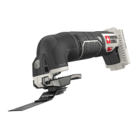
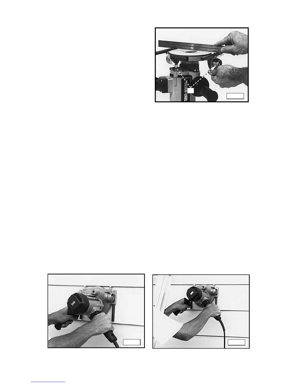
To sand the lower part of wide clapboards, move the tool down and up, back
and forth from left to right, and in circles. To spot sand from a ladder, firmly
anchor the ladder close enough to the work area to prevent excessive reach.
Work with one arm outside one of the legs of the ladder and the other
between the rungs of the ladder (Fig. 14).
Fig. 12
Fig. 13
Fig. 14
A