5
Proper Attachment of Gas Cylinders
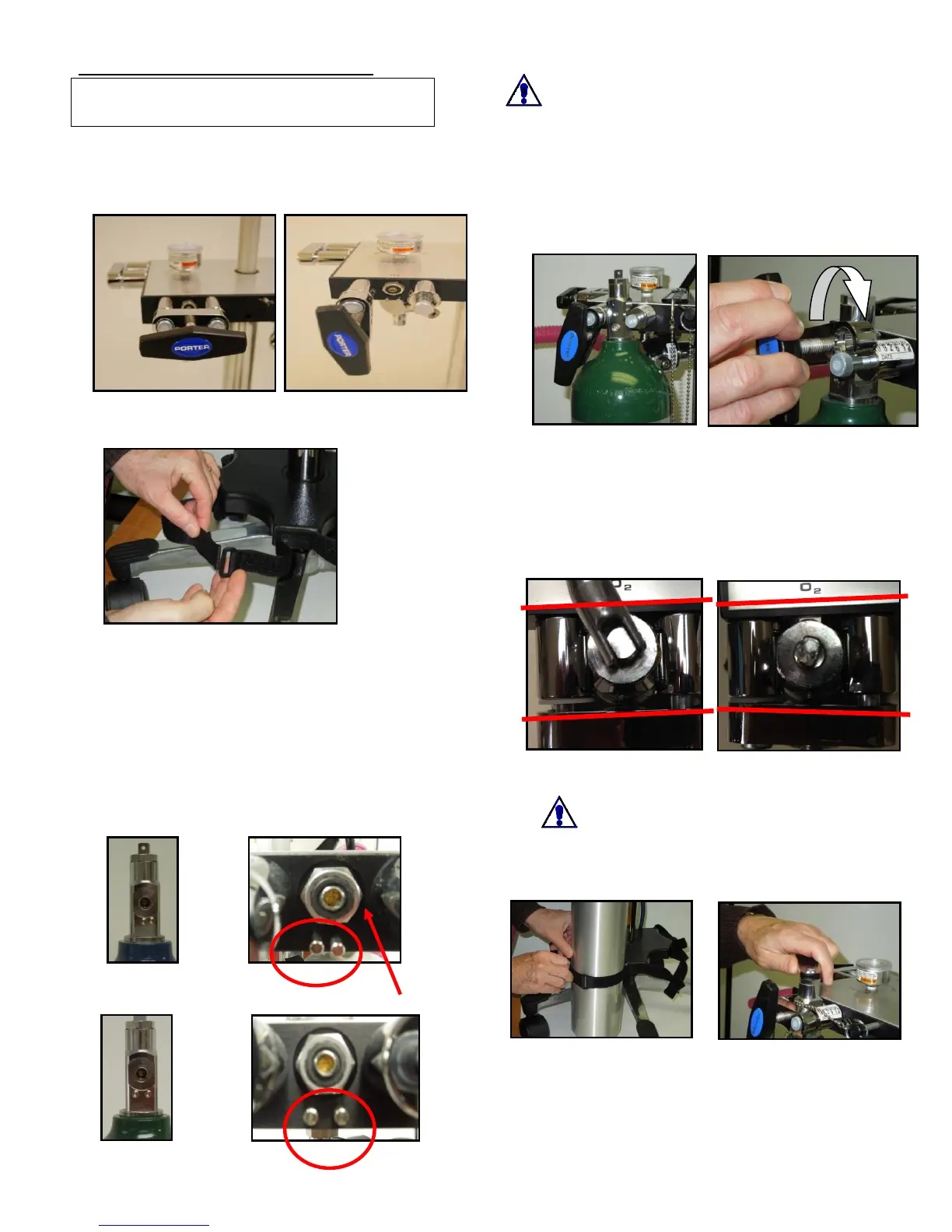
1. Loosen the Tee Handle (Fig. 3.1) until point is
even with the inside of the Swivel Arm. Push Tee
Handle inwards to flip to open position. Align
Tee Handle vertically (Fig. 3.2).
2. Undo the Hook & Loop straps on the Cylinder
Restraint (Fig. 3.3)
3. Cylinder Preparation: Remove any plastic
wrap/washer from the top of cylinder. Verify that
the rubber washer (Fig. 3.5) provided with the E-
Stand is still in place. Use the rubber E-Stand
washer (replace once/yr.).
4. Mount the “E” cylinders of Oxygen and Nitrous
Oxide (not included) to the E-Stand Block. Insert
cylinders correctly on indexing pins and as
marked on Block (N
2
O Figs. 3.4, 3.5; O
2
Figs.
3.6, 3.7). Pins assure mounting in appropriate
position.
N
2
O pins Rubber
Washer
O
2
Pins
Warning
Do not remove or alter gas indexing pins
Verify correct pin locations per
illustrations.
5. Slide the cylinder into place by lining up the pins
and pin holes on the cylinder. Push into place.
Properly placed, the cylinder should hang on the
pins (Fig. 4).
6. Cylinders should hang freely between wheel
base. If the wheel base interferes, loosen and
rotate cylinder restraint.
7. Push inwards & Rotate swivel clockwise to close
(Fig. 5.1). Pull fully outwards on Tee Handle and
swivel will lock in place. Assure swivel is in
parallel alignment with E-Block surface (Figs. 5.2,
5.3). Gaps between swivel and posts should be
equal on both sides and the bolt head should not
be evident.
Fig. 5.2 Aligned Fig. 5.3 Misaligned
8. Swivel should stay in the locked aligned position
when Tee Handle is tightened securely.
Warning: Tee Handle not tightened
securely may result in cylinder
leakage with possible loud hissing or
popping sounds. Close cylinder valve and follow
procedures to correctly align and tighten Tee
Handle.
9. Secure the Hook & Loop straps to hold cylinder in
place (Fig. 5.4).
10. The Valve Wrench (hanging from black Knob) is
used to open/close Cylinder Valves (Fig. 6).
Caution: When removing cylinders, always
be sure valves are closed tightly.
 Loading...