MFG. #5471131 - REV M
2/08
PRINTED IN USA PAGE 2 OF 4
QRS
QUICK RELEASE SWITCH
OUTGOING
INCOMING
DWG# 923-3
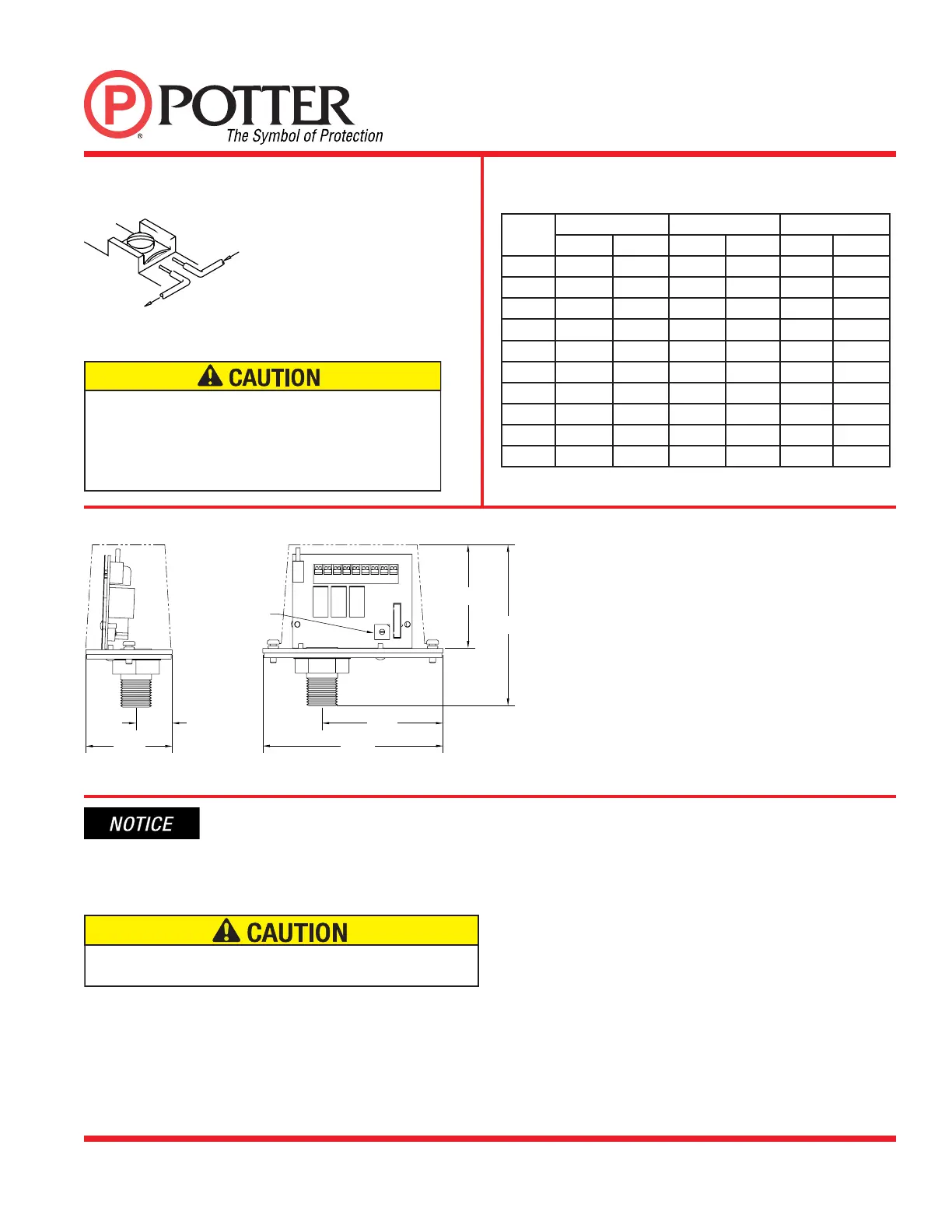
Switch Terminal Connections
Clamping Plate Terminal
An uninsulated section of a single conductor should not
be looped around the terminal and serve as two separate
connections. The wire must be severed, thereby providing
supervision of the connection in the event that the wire
becomes dislodged from under the terminal.
Dimensions
2.250
(5.7 cm)
1.125
(2.9 cm)
PRESSURE
SETTING
SWITCH
4.750
(12.1 cm)
3.188
(8.1 cm)
DWG #1131-2
2.750
(7.0 cm)
4.250
(10.8 cm)
Switch
Setting
Low Air Threshold
Nominal Pressure
High Air Threshold
PSI BAR
PSI
BAR PSI BAR
0 7 .48
10
.69 15 1.04
1 7 .48
15
1.04 20 1.38
2 15 1.04
20
1.38 25 1.72
3 15 1.04
25
1.72 30 2.07
4 20 1.38
30
2.07 35 2.41
5 25 1.72
35
2.41 40 2.76
6 30 2.07
40
2.76 45 3.10
7 35 2.41
45
3.10 50 3.45
8 45 3.10
55
3.79 60 4.14
9 55 3.79
65
4.48 70 4.83
System Air Pressure Setting Chart
Switch is factory set on position #4 for normal air pressure of 30 PSI.
The following installation requirements shall be followed completely
to ensure proper operation of the QRS and PFC-4410-RC. Make all
connections between the QRS and PFC-4410RC with no power applied
to the PFC-4410RC.
Failure to follow these requirements completely will result
in improper operation.
1. There shall be a continuous run of shielded cable between the QRS
& PFC-4410-RC. Splices shall not be permitted. If an 8 conductor
shielded cable is not available, multiple cables may be used to provide
the number of conductors required, providing all cables are shielded.
2. All wiring between the QRS and PFC-4410-RC shall be installed
in a continuous run of metal conduit. Interruptions in the continuity of
the metal conduit shall not be permitted. There shall not be any other
wires in, or attached to, this conduit. If a junction box is used, the box
shall be of the drawn style, not spot welded. There shall be no gaps in
the box. The metal box cover shall remain on at all times.
3. The drain wire of the shielded cable shall be grounded at the PFC-
4410-RC only. It shall not be grounded at the QRS. Termination of
the drain wire at the QRS shall consist of cutting the wire short and
insulating it to prevent contact with other material or circuits.
4. The drain wire of the shielded cable shall be connected to the S
terminal on the RS-485 terminal strip in the PFC-4410-RC. The drain
wire shall be as short as possible and insulated to prevent unwanted
contact with other circuits on the 4410-RC.
5. Terminals 8 & 9 of the QRS shall be connected to the + - terminals
of the 24VDC power terminal strip respectively in the PFC-4410-RC,
to supply power to the QRS. These connections must be made before
applying power to the PFC-4410RC.
6. The 120VAC power for the PFC-4410-RC shall be from a dedicated
circuit. There shall not be any other conductors in the conduit other than
the hot, neutral and ground wires necessary to power the PFC-4410-RC.
 Loading...