MFG. #5400932 - REV D
1/08
PRINTED IN USA PAGE 2 OF 3
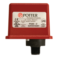
PS100-2
PRESSURE TYPE FLOW SWITCH
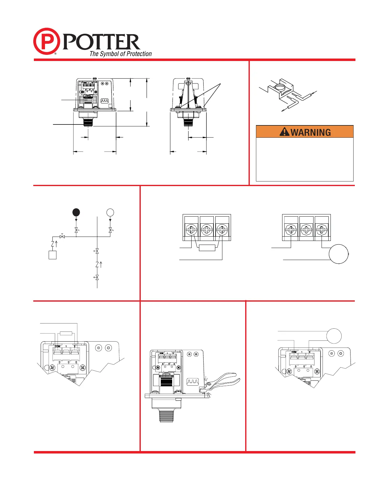
Typical Sprinkler Applications
Switch Clamping Plate Terminal
Dimensions
OUTGOING
INCOMING
DWG# 923-3
Fig. 1
Fig. 2
Fig. 3
GROUND
SCREWS
1/2" NPT
PS100
PRESSURE
DROP ALARM
SWITCH
SHUT-OFF
VA LV E
BLEEDER
TEST VALVE
BVL
CHECK
VA LV E
EXCESS
PRESSURE
PUMP
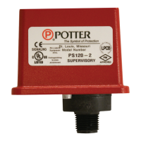
PS120 PRESSURE
SUPERVISORY
SWITCH
BLEEDER
TEST VALVE
BVL
DWG #925-1A
OS & Y
VA LV E
OS & Y
VA LV E
CHECK
VA LV E
WAT ER
SUPPLY
NOTE: To prevent leakage, apply teflon tape sealant to male threads only.
ADJUSTMENT
KNOB
2.87
[72.97]
4.22
[107.19]
2.48
[62.87]
3.78
[95.89]
3.20
[81.28]
1.60
[40.64]
Fig. 4
BELL
COM 1 2COM 1 2
EOLR
TO FIRE
ALARM
PANEL
POSITIVE DC
OR HOT AC
NEGATIVE DC OR
NEUTRAL AC
LINE
LOAD
OPEN CIRCUIT CLOSES ON ALARM
RING A LOCAL BELL
WITH NORMAL
SYSTEM
PRESSURE
APPLIED
-TERMINAL
2 CLOSES ON
PRESSURE DROP.
An uninsulated section of a single conductor
should not be looped around the terminal and
serve as two separate connections. The wire
must be severed, thereby providing supervision
of the connection in the event that the wire
becomes dislodged from under the terminal.
Typical Connections
Break out thin section of divider to
provide path for wires when wiring both
switches from one conduit entrance.
One Conduit Wiring
Fig. 6
Waterfl ow Signal Connection
EOLR
TO FIRE ALARM PANEL
Fig. 5
Fig. 7
Local Bell For Waterfl ow Connection
POSITIVE DC
OR HOT AC
BELL
NEGATIVE DC
OR NEUTRAL AC
LINE
LOAD