MFG. #5400930 - REV E
09/12
PRINTED IN USA PAGE 1 OF 3
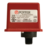
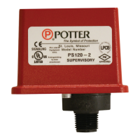
PS40 SERIES
SUPERVISORY PRESSURE SWITCH
Installation
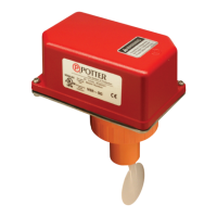
The Potter PS40 Series Supervisory Pressure Actuated Switches are designed
primarily to detect an increase and/or decrease from normal system pressure
in automatic re sprinkler systems. Typical applications are: Dry pipe
systems, pre-action air/nitrogen supervision, pressure tanks, air supplies,
and water supplies. The PS40 switch is factory set for 40 PSI (2,8 BAR)
normal system pressure. The switch marked with the word LOW is set to
operate at a pressure decrease of 10 PSI (,7 BAR) at 30 PSI (2,1 BAR). The
switch marked with the word HIGH is set to operate at a pressure increase
of 10 PSI (,7 BAR) at 50 PSI (3,5 BAR). See section heading Adjustments
and Testing if other than factory set point is required.
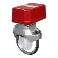
1. Connect the PS40 to the system side of any shutoff or check valve.
2. Apply Teon tape to the threaded male connection on the device.
(Do not use pipe dope)
3. Device should be mounted in the upright position.
(Threaded connection down)
4. Tighten the device using a wrench on the ats on the device.
Wiring Instructions
1. Remove the tamper resistant screw with the special key provided.
2. Carefully place a screwdriver on the edge of the knockout and sharply
apply a force sufcient to dislodge the knockout plug. See Fig. 9
3. Run wires through an approved conduit connector and afx the
connector to the device. A NEMA-4 rated conduit tting is
required for outdoor use.
UL, cUL, and CSFM Listed, FM and LPC Approved, NYMEA
Accepted, CE Marked
Dimensions: 3.78" (9,6cm)W x 3.20" (8,1cm)D x 4.22" (10,7cm)H
Conduit Entrance: Two knockouts provided for 1/2" conduit. Individual
switch compartments and ground screw suitable for
dissimilar voltages
Enclosure: Cover- Die-cast with textured red powdercoat nish, single
cover screw and rain lip.
Base- Die-cast
Pressure Connection: Nylon 1/2" NPT male
Factory Adjustment: PS40-1 operates on decrease at 30 PSI (2,1 BAR)
PS40-2 operates in increase at 50 PSI (3,5 BAR)
and on decrease at 30 PSI (2,1 BAR)
Pressure Range: 10-60 PSI (,7 - 4,1 BAR)
Differential: Typical 1 lb. at 10 PSI (,07 at ,7 BAR)
4 lbs at 60 PSI (,28 at 4,1 BAR)
Maximum System Pressure: 300 PSI (20,68 BAR)
Switch Contacts: SPDT (Form C)
10.1 Amps at 125/250VAC, 2.0 Amps at 30VDC
One SPDT in PS40-1, Two SPDT in PS40-2
Environmental Specications:
NEMA 4/IP66 Rated Enclosure - indoor or outdoor when used
with NEMA 4 conduit ttings.
Temperature range: -40°F to 140°F (-40°C to 60°C)
Tamper: Cover incorporates tamper resistant fastener that requires a
special key for removal. One key is supplied with each device.
For optional cover tamper switch kit, order Stock No. 0090200.
See bulletin #5401200 PSCTSK.
Service Use:
Automatic Sprinkler NFPA-13
One or two family dwelling NFPA-13D
Residential Occupancy up to four stories NFPA-13R
National Fire Alarm Code NFPA-72
Potter Electric Signal Company, LLC • St. Louis, MO • Phone: 866-956-0988/Canada 888-882-1833
• www.pottersignal.com
Ordering Information
Model Description Stock No.
PS40-1 Pressure switch with one set SPDT contacts 1340403
PS40-2 Pressure switch with two sets SPDT contacts 1340404
Hex Key 5250062
Cover Tamper Switch Kit 0090200
BVL Bleeder valve 1000018
4. Connect the wires to the appropriate terminal connections for the
service intended. See Figures 2,4,5,6, and 8
Adjustment And Testing
The operation of the pressure supervisory switch should be tested upon
completion of installation and periodically thereafter in accordance with
the applicable NFPA codes and standards and/or the authority having
jurisdiction (manufacturer recommends quarterly or more frequently).
Note: Testing the PS40 may activate other system connected devices.
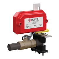
The use of a Potter BVL (see product bulletin 8900067 for details) is
recommended to facilitate setting and testing of the PS40 pressure switch.
When a BVL (bleeder valve) is used, the pressure to the switch can be
isolated and bled from the exhaust port on the BVL without effecting the
supervisory pressure of the entire system. See Fig. 3
The operation point of the PS40 Pressure Switch can be adjusted to any
point between 10 and 60 PSI (0,7 - 4,11 BAR) by turning the adjustment
knob(s) clockwise to raise the actuation point and counter clockwise to
lower the actuation point. In the case of the PS40-2, both switches operate
independent of each other. Each switch may be independently adjusted to
actuate at any point acrosss the switch adjustment range. Initial adjustment
can be made with a visual reference from the top of the adjustment knob
across to the printed scale on the switch bracket. Final adjustments should
be veried with a pressure gauge.