EasyManuals Logo

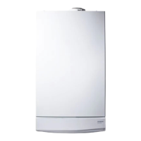
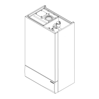
Potterton Promax 24 Combi ErP User Manual

Potterton Promax 24 Combi ErP
56 pages
To Next Page IconTo Next Page
To Previous Page IconTo Previous Page
Page #45 background imageLoading...
Page #45 background image
45
© Baxi Heating UK Ltd 2016
15.0 Electrical
15.1 Illustrated Wiring Diagram
- brown
- black
- blue
- white
br
bk
b
w
- green
- green / yellow
- red
g
g/y
r
Control PCB
X2 X3
X9
X501
1 21 23
3
44
5
5
6789
X1
1 2
DHW
NTC Sensor
Central Heating
NTC Sensor
Fan
Gas Valve
Overheat Stat
Flame
Sensing
Electrode
Pump
(Grundfos)
Flue Sensor
X400
X401
g
g
b
b
r
r
b
b
b
b
b
b
br
bk
g
b
br
g/y
b
br
b
br
br
b
b
br
br
b
b
br
r
bk
r
bk
Water Pressure
Switch
Spark
Generator
Ignition
Electrode
9876
54321
910876
54321
Hall Effect
Sensor
r
w
b
w
r
bk
bk
r
w
Diverter Valve
1
2
3
4
1 234
bk
br
bk
b
N
L
w
g or w
1
4
2
5
3
1
2
a
b
Link
bk
b
g/y
br
Mains Input Cable
br
b
b
br
Pump
PCB
Timer (where fitted)
X1
X2
X3
g/y
6 Way
Connector
br
b
Air
Pressure
Switch
2 1
Pump
(Wilo)
br
b
g/y

Questions and Answers:

Question and Answer IconNeed help?

Do you have a question about the Potterton Promax 24 Combi ErP and is the answer not in the manual?

Potterton Promax 24 Combi ErP Specifications

General IconGeneral
BrandPotterton
ModelPromax 24 Combi ErP
CategoryBoiler
LanguageEnglish

Related product manuals