POWER DRIVE SYSTEMS
DUNLITE UVR100 AUTOMATIC VOLTAGE REGULATOR
2
NOTE
When the regulator is fitted within a separate control cubicle, the terminals U, V, W and N will have been
factory connected to AC supply points within the cubicle.
Similarly, the voltage adjustment terminals PP may have been connected to a separate potentiometer -
normally these terminals will be bridged, as will also the droop circuit terminals D1, D2.
The only terminals requiring connection when installing the plant will be the F+ and F- (grey and white
respectively) and a small terminal block is fitted within the alternator terminal box for interconnection
purposes.
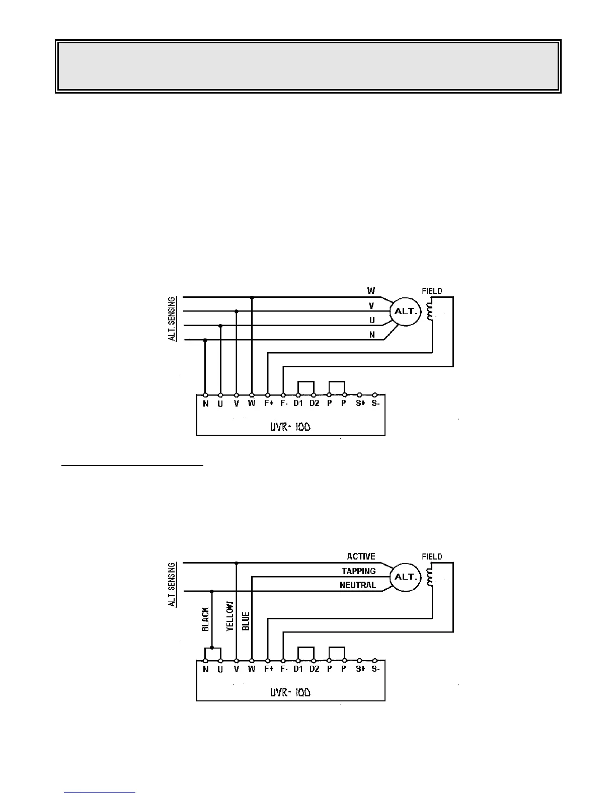
Once the above has been completed, the regulator may be connected to the alternator. N to neutral, U to
Red phase, V to White phase, W to Blue phase, F+ and F- to Field. D1 D2 and PP must be bridged if not
connected to external potentiometers ~ see diagram.
Note: Later model UVR100 regulator violet wires to S+ & S (See SCOOP Section)
SINGLE PHASE OPERATION
As for three phase operation, the regulator must be adjusted for either 240 or 120 volt sensing. This can be
done by the purple fly lead as for three phase operation.
For single phase operation, terminals N and U are bridged and connected to neutral, terminals V and W
are bridged and connected to the alternator sensing. The remaining terminals are connected as for three
phase operation. See diagram.
_____________________________________________________________________________________
 Loading...