POWER DRIVE SYSTEMS
DUNLITE UVR100 AUTOMATIC VOLTAGE REGULATOR
5
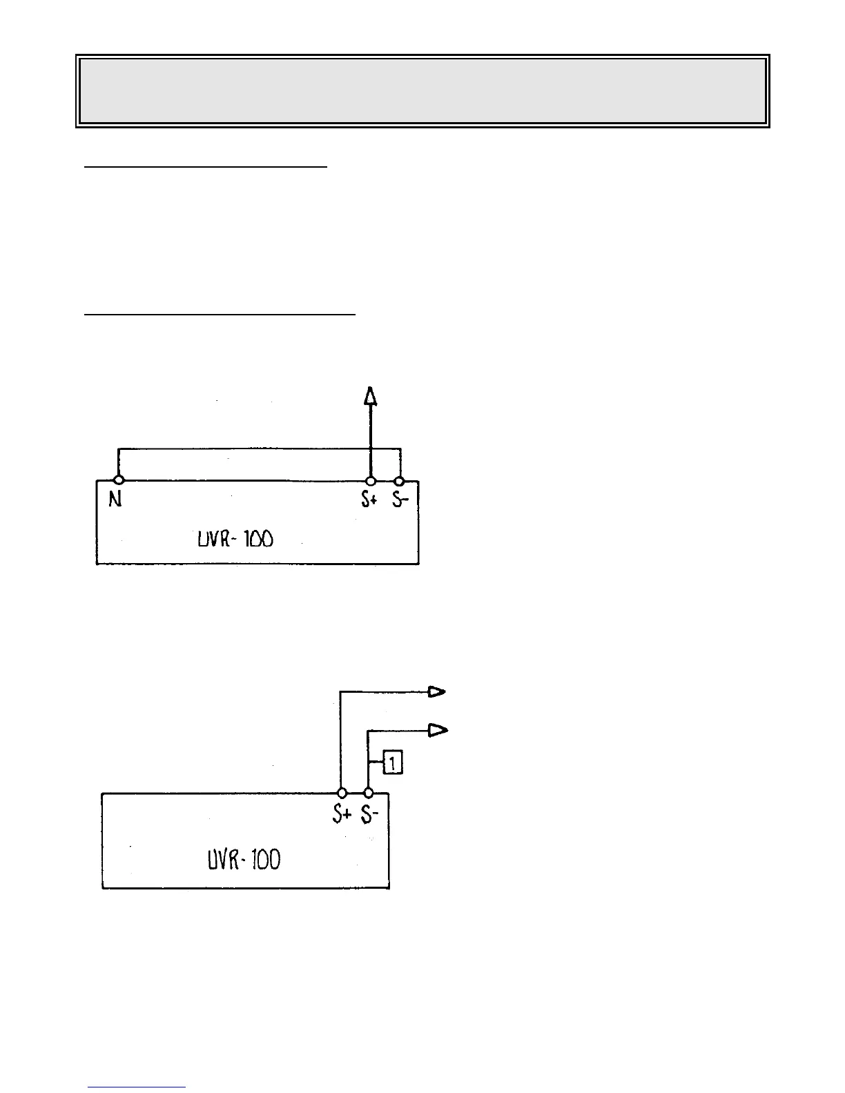
SCOOP REMOTE INDICATION S+ S- (Later models)
S+ and S- terminal s are used for remote indication of the SCOOP operation. The output is an optically
coupled silicon NPN phototransistor. The ouput is connected via the alternator terminal box to a Series
2000 control which has the necessary interface.
If SCOOP trips as per normal overload protection etc. the opto coupled transistor will switch and shut the
engine down. (See operating manual Series 2000 MK III).
Connection details SCOOP S+ S-
To No. 7 engine terminal
Series 2000 control cubicle
Figure 1
Connect as for Figure 1 when neutral and battery negative are common to earth.
To No. 7 engine terminal
To No. 1 engine terminal
Battery negative
Series 2000 control cubicle
Figure 2
Connect as for Figure 2 when separate neutral and battery negative is required.
Battery negative is earthed.
_____________________________________________________________________________________
 Loading...