PREPARATION FOR INSTALLING THE EQUIPMENT
Charging current adjustment
NB Wall has a selector to limit the maximum charging current to the corresponding current available in
the installation. This section indicates its location and adjustment.
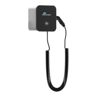
On the following image, the selector on the control card is highlighted:
The relation between the position of the selector with the maximum charging current for each charging
hose is as follow:
Notes:
• Options 0 to B require each machine to have an individual connection.
• Options C and D allow both hoses to be run on a single inlet, sharing the current equally between
the two hoses if both are running and providing the maximum current value if only one is running.
The maximum allowed current value of the charger (32 A), position B of the selector, is set as factory
default.