Do you have a question about the Power-Genex ASD-5000 Series and is the answer not in the manual?
Defines Caution, Warning, and Danger levels for potential hazards.
User's responsibility for product compatibility and system design.
Emphasizes operation by trained personnel only.
Safety measures for inspection and maintenance procedures.
Conditions requiring special consideration before use.
Product intended for manufacturing industries; warranty terms and disclaimers apply.
Prohibits use for WMD manufacturing and outlines export regulations.
Critical warnings for safe operation of the positioner.
Precautions for safe operation and handling.
General precautions for users of the positioner.
Precautions regarding vibration, impact, moisture, and magnetic fields.
Requirements for clean, dry, and dust-free compressed air.
Guidelines for operating temperature, corrosive atmospheres, etc.
Safety steps for maintenance and electrical modifications.
Warnings and precautions for electrostatic discharge.
Requirements for intrinsic safety and proper earthing.
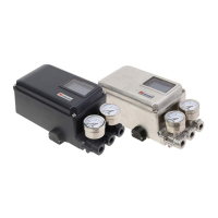
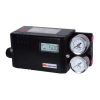
Lists the main components of the ASD-5000 positioner.
Diagram and labels identifying external parts of the positioner.
Details on input signal range, HART, and output specifications.
Instrument air requirements and compatible actuator types.
Environmental influences and feedback options.
Enclosure details, protection class, and hazardous area certifications.
Explanation of the model code for ordering the positioner.
Illustrates an example of a complete order code.
Detailed explanation of information found on the product nameplate.
Block diagram illustrating the device's operating principle.
Identifies and labels the elements shown on the LCD display.
Details various display modes for the LCD screen.
Information on supported languages for the display.
General instructions for mounting to linear actuators.
Steps for installing the follower guide component.
Procedure for installing the feedback lever and mounting bracket.
Instructions for mounting onto cast yoke or pillar yoke.
Guidance for mounting on alternative cast yoke designs.
Instructions for mounting the positioner on diaphragm actuators.
Details on installing the feedback pin follower guide.
Step-by-step guide for standard installation.
Specifies the maximum allowable operating angle for the valve.
Correct placement of the valve stem pin on the feedback lever.
Visual guidance on proper installation orientation.
Confirms support for NAMUR mounting standards.
Steps for assembling and connecting to rotary actuators.
Specific instructions for mounting with a fork lever.
Guidance on setting the correct position of the fork lever.
Instructions for re-assembling the multi-size bracket.
Basic guidelines for air filter, quality, and pressure.
Diagrams for direct and reverse acting linear connections.
Air connection diagrams for rotary actuators.
Guidance on using orifices to prevent hunting.
Explanation of the auto/manual mode switch.
Diagram showing the terminal block layout.
Wiring instructions for input and output signals.
Wiring for wet contact alarm limits.
Wiring for dry contact limit switches (SPDT, P&F).
Instructions for internal and external earthing.
General rules and precautions for intrinsic safety wiring.
Specific wiring for intrinsic safety input signals.
Specific wiring for intrinsic safety output signals.
Intrinsic safety wiring for alarm limits.
Intrinsic safety wiring for SPDT switches.
Intrinsic safety wiring for P&F proximity sensors.
Instructions for installing cable glands.
Instructions for installing blind plugs.
Steps to start the auto-calibration process.
How to switch between different display configurations.
Diagram showing the hierarchical structure of parameters.
Parameters for controlling display variables.
Parameters for manual operation and monitoring.
Parameters for auto-tuning and general settings.
Parameters for testing and locking functions.
Detailed settings for input, PID, and dead band.
Parameters for speed, damping, sensitivity, and linearization.
Parameters accessible via the sub-menu.
How to enable or disable parameter locking.
Options for changing the display mode and values.
Procedure for operating the valve manually.
How to check status, errors, and mileage.
Details on performing auto-calibration.
Resets all settings to factory defaults.
Recalibrates the start and end points of the valve.
Restarts the positioner program.
Steps to execute a valve test.
Procedure to verify correct installation status.
Diagram illustrating the main menu structure.
Flow diagram showing parameter categories.
Configures the input signal type (4-20mA or 20-4mA).
Describes how the positioner responds to input signals.
Sets the valve control to a linear characteristic.
Allows selection and adjustment of shape modes for valve curves.
Enables user to create custom valve characteristic curves.
Sets the maximum range of valve opening.
Sets the dead band to account for SV/PV differences.
Introduction to adjusting PID gain parameters.
Adjusting the proportional gain for control.
Adjusting the integral gain for control.
Adjusting the differential gain for control.
Adjusts the response speed of the actuator.
Sets the first damping limit for control range.
Sets the second damping limit for control.
Adjusts the sensitivity based on actuator size.
Auto-compensation for feedback lever pin position.
Fine-tunes position control for improved accuracy.
Lists parameters available within the sub-menu.
Safety function to ensure the valve closes completely.
Configures the output signal for position transmitter function.
Allows changing the orientation of the LCD display.
Sets software-based alarm limits for 24VDC outputs.
Matches calibrator signals to positioner settings.
Selects the HART communication polling address.
Sets parameters for Partial Stroke Testing.
Adjusts the valve response time during PST.
Displays readings from internal pressure sensors.
Checks for voltage, connections, and air quality before maintenance.
Identifies key spare parts with part numbers.
Step-by-step guide for replacing the pilot valve.
Step-by-step guide for replacing the torque motor.
Comprehensive list of available spare parts.
Technical drawings and measurements for the linear type.
Technical drawings and measurements for the rotary type.
Details on the product's warranty period and conditions.
Information on how to contact support for service.
| Input Signal | 4-20 mA |
|---|---|
| Supply Pressure | 1.4 - 7 bar (20 - 100 psi) |
| Protection | IP66 |
| Enclosure Rating | NEMA 4X, IP66 |
| Housing Material | Aluminum |