K
kevin29Aug 1, 2025
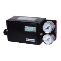
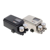
How to fix Fee FBFT error on Power-Genex SS3L?
- TtravissandovalAug 1, 2025
If you encounter 'Fee FBFT' with your Power-Genex Valve Positioners, it indicates a defect in the potentiometer socket contact or PCB board. You should check the potentiometer assembly and the board.