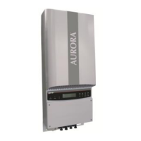
TRIO-5.8-TL-OUTD-400 / TRIO-7.5-TL-OUTD-400 / TRIO-8.5-TL-OUTD-400
1.
2.
3.
4.
5.
L
ifting and transport
I
nstruments
Assembly Instruction
Opening the cover
Inverter Models and ComponentsChoice of installation location
Labels and Symbols
7.
8.
9.
Line cable and protection devices
Quick Installation Guide
In addition to what is explained below, the safety and installation information provided in
the installation manual must be read and followed. The technical documentation and the
interface and management software for the product are available at the website http://
www.power-one.com
The device must be used in the manner described in the manual. If this is not the case the
safety devices guaranteed by the inverter might be ineective.
This new generation three-phase inverter for domestic installations, is available in three power ratings: 5.8,
7.5 and 8.5 kW. The compact, transformerless TRIOs are the latest products in the Aurora family for their
performance, ease of use and installation, monitoring and control. The topology of the TRIO 20.0/27.6 inverters
has been redesigned to ensure that the TRIO 5.8/7.5/8.5 models also enjoy high conversion eciency across
a wide range of input voltages, and the double MPPT gives maximum installation exibility for an optimal
energy production (TRIO 7.5/8.5 models).
FEATURES
• High speed and precise MPPT algorithm for real time power tracking and improved energy harvesting
• Wide input voltage range
• Two independent MPPT channels for TRIO-7.5/8.5 allows optimal energy harvesting from two sub- arrays
oriented in dierent directions (one MPPT channel for TRIO-5.8)
• Flat eciency curves ensure high eciency at all output levels ensuring consistent and stable performance
across the entire input voltage and output power range
• Datalogger and smart grid functionalities integrated on expansion cards:
• PMU expansion card option, with external sensors inputs for monitoring environmental conditions
and additional RS-485 for Modbus protocol
• Ethernet expansion card option with integrated Web Server and remote monitoring capability via
Web Portal (Modbus/TCP supported)
• Remote inverter upgrade
• Reactive power management
• Availability of auxiliary DC output voltage (24V, 100mA)
• Natural convection cooling for maximum reliability
• Outdoor enclosure for unrestricted use under any environmental conditions (IP65)
• Sliding cover for the easiest installation and maintenance
• No compulsory maintenance is required
TRIO-5.8_7.5_8.5-TL-OUTD-Quick Installation Guide EN RevA
Transport and handling
Transport of the equipment, especially by road, must be carried out with by suitable ways and means for protecting the
components (in particular, the electronic components) from violent shocks, humidity, vibration, etc.
Lifting
Where indicated and/or where there is a provision, eyebolts or handles, which can be used as anchorage points, are inserted and/
or can be inserted.
The ropes and means used for lifting must be suitable for bearing the weight of the equipment.
Unpacking and checking
The components of the packaging must be disposed on in accordance with the regulations in force in the country of installation.
When you open the package, check that the equipment is undamaged and make sure all the components are present.
If you nd any defects or damage, stop unpacking and consult the carrier, and also promptly inform the Service Power-One.
Equipment weight
Model Mass weight Lifting points n°#
TRIO-5.8-TL-OUTD(-S)-400 25 kg 4
TRIO-7.5-TL-OUTD(-S)-400 28 kg 4
TRIO-8.5-TL-OUTD(-S)-400 28 kg 4
The labels on the inverter have the Agency marking, main technical data and identication of the equipment and manufacturer
The labels attached to the
equipment must NOT be re-
moved, damaged, dirtied,
hidden,etc...
If the service password is requested, use the serial number eld -SN: SSSSSSSSSS- shown on the identication label
(axed to the side)
In the manual and/or in some cases on the equipment, the danger or hazard zones are indicated with signs, labels, symbols or icons.
Always refer to instruction
manual
General warning - Important
safety information
Hazardous voltage Hot surfaces
IP65
Protection rating of
equipment
Temperature range
Without isolation transformer
Direct and alternating cur-
rents, respectively
Positive pole and negative
pole of the input voltage (DC)
Always use safety clothing
and/or personal safety devi-
ces
Point of connection for groun-
ding protection.
Time need to discharge stored
energy
Power-One
TRIO-XX.X-XX-XXXX-XXX-XXX
P/N:PPPPPPPPPPP SN:SSSSSSSSSS WK:WW/YY
XXXXXXXXX Q1
01
02 03 04
01
Inverter model
02
Inverter Part Number
03
Inverter Serial Number
04
Week/Year of manufacture
Wall mounting
During installation do not place the inverter
10
with the front cover
04
facing towards the ground.
•Positionthebracket
13
perfectly level on the wall and use it as a drilling
template.
•Drillthe4holesrequiredusingadrillwith10mmbit.Theholesmustbe
about 70mm deep.
•Fixthebrackettothewallwiththe4wallanchors,10mmindiameter,
supplied.
•Attachtheinverterbyinsertingthetwotabsonthebracket
13
into the
2slots on the inverter (gures A1 and A2).
• Secure the inverter to the bracket by screwing the 2 lock screws
14
onboth sides of the inverter (gure A3).
•Unscrewthe8screwsandopenthefront cover
04
as described in the fol-
lowing paragraph to make all necessary connections. The cover is tted
into xed rails and cannot be removed.
The models of inverter to which this guide refers are available in 3 power ratings: 5.8 kW, 7.5 kW
e 8.5 kW.
For inverters of equal output power the variant between the various models is the presence or
lack thereof, of the DC disconnect switch
08
.
TRIO-5.8-TL-OUTD-400 TRIO-5.8-TL-OUTD-S-400
•Numberofinputchannels:1
•DCdisconnectswitch
08
: No
•Input connectors: screw terminal block
•Numberofinputchannels:1
DC disconnect switch
08
: Yes
Input connectors: quick t connectors (2 pai-
rs)
TRIO-7.5-TL-OUTD-400
TRIO-8.5-TL-OUTD-400
TRIO-7.5-TL-OUTD-S-400
TRIO-8.5-TL-OUTD-S-400
•Numberofinputchannels:1
•DCdisconnectswitch
08
: No
•Input connectors: screw terminal block
•Numberofinputchannels:1
DC disconnect switch
08
: Yes
Input connectors: quick t connectors (2 pai-
rs)((2 pairs per channel)
Main components
01
Display
11
Handles
02
LED panel
12
Heat sink
03
Keypad
13
Bracket
04
Front cover
14
Locking screw
05
AC output board
15
AC cable gland
06
Communication and control board
16
Service cable glands
07
Scheda di ingresso DC
17
Anticondensation valve
08
DC disconnect switch
18
DC cable glands
09
bracket mounting slot
19
Input connectors (MPPT1)
10
Inverter
20
Input connectors (MPPT2)
50
cm
50
cm
15cm
15cm
TRIO
POWER ALARM GFI ESC UP DOWN ENTER
DC
AC
DC
AC
TRIO
POWER ALARM GFI ESC UP DOWN ENTER
DC
AC
DC
AC
TRIO
POWER ALARM GFI ESC UP DOWN ENTER
DC
AC
DC
AC
TRIO
POWER ALARM GFI ESC UP DOWN ENTER
DC
AC
DC
AC
TRIO
POWER ALARM GFI ESC UP DOWN ENTER
DC
AC
DC
AC
TRIO
POWER ALARM GFI ESC UP DOWN ENTER
DC
AC
DC
AC
TRIO
POWER ALARM GFI ESC UP DOWN ENTER
DC
AC
DC
AC
TRIO
POWER ALARM GFI ESC UP DOWN ENTER
DC
AC
DC
AC
TRIO
POWER ALARM GFI ESC UP DOWN ENTER
DC
AC
DC
AC
TRIO
POWER ALARM GFI ESC UP DOWN ENTER
DC
AC
DC
AC
TRIO
POWER ALARM GFI ESC UP DOWN ENTER
DC
AC
DC
AC
TRIO
POWER ALARM GFI ESC UP DOWN ENTER
DC
AC
DC
AC
TRIO
POWER ALARM GFI ESC UP DOWN ENTER
DC
AC
DC
AC
50
cm
50
cm
15cm
15cm
TRIO
POWER ALARM GFI ESC UP DOWN ENTER
DC
AC
DC
AC
TRIO
POWER ALARM GFI ESC UP DOWN ENTER
DC
AC
DC
AC
TRIO
POWER ALARM GFI ESC UP DOWN ENTER
DC
AC
DC
AC
TRIO
POWER ALARM GFI ESC UP DOWN ENTER
DC
A
C
DC
AC
TRIO
POWER ALARM GFI ESC UP DOWN ENTER
DC
AC
DC
AC
TRIO
POWER ALARM GFI ESC UP DOWN ENTER
D
C
AC
DC
AC
TRIO
POWER ALARM GFI ESC UP DOWN ENTER
D
C
AC
DC
AC
TRIO
POWER ALARM GFI ESC UP DOWN ENTER
DC
AC
DC
AC
TRIO
POWER ALARM GFI ESC UP DOWN ENTER
DC
AC
DC
AC
TRIO
POWER ALARM GFI ESC UP DOWN ENTER
DC
AC
DC
AC
TRIO
POWER ALARM GFI ESC UP DOWN ENTER
DC
AC
DC
AC
TRIO
POWER ALARM GFI ESC UP DOWN ENTER
DC
AC
DC
AC
TRIO
POWER ALARM GFI ESC UP DOWN ENTER
DC
AC
DC
AC
®
MODEL:
TRIO-5.8-TL-OUTD-X-400
-25 to + 60 °C
-13 to +140 °F
IP65
10 minutes
V
DC max
I
DC max
1000 V
V
DC MPP
200-950 V
18.9 A
V
DC, Full Power
320-800 V
I
SC max
24 A
Made in Italy
DINVVDE 0126-1-1
PROTECTIVE CLASS: I
AURORA
PHOTOVOLTAIC INVERTER
®
V
AC nom
f
nom
I
AC max
P
acr (cos =
±
0.9)
φ
400 V 3Ø, 3W+N+PE
50 Hz
5220 W @ 50 °C amb.
P
acr (cos
φ
= 1)
5800 W@50 °C amb.
10 A
®
MODEL:
TRIO-7.5-TL-OUTD-X-400
-25 to + 60 °C
-13 to +140 °F
IP65
10 minutes
V
DC max
I
DC max
1000 V
V
DC MPP
200-950 V
2 x 15 A
V
DC, Full Power
320-800 V
I
SC max
2x20 A
Made in Italy
DINVVDE 0126-1-1
PROTECTIVE CLASS: I
AURORA
PHOTOVOLTAIC INVERTER
®
V
AC nom
f
nom
I
AC max
P
acr (cos =
±
0.9)
φ
400 V 3Ø, 3W+N+PE
50 Hz
6750 W @ 50 °C amb.
P
acr (cos
φ
= 1)
7500 W@50 °C amb.
12.5 A
®
MODEL:
TRIO-8.5-TL-OUTD-X-400
-25 to + 60 °C
-13 to +140 °F
IP65
10 minutes
V
DC max
I
DC max
1000 V
V
DC MPP
200-950 V
2 x 15 A
V
DC, Full Power
320-800 V
I
SC max
2x20 A
Made in Italy
DINVVDE 0126-1-1
PROTECTIVE CLASS: I
AURORA
PHOTOVOLTAIC INVERTER
®
V
AC nom
f
nom
I
AC max
P
acr (cos =
±
0.9)
φ
400 V 3Ø, 3W+N+PE
50 Hz
7650 W @ 50 °C amb.
P
acr (cos
φ
= 1)
8500 W@50 °C amb.
14.5 A
TRIO
POWER ALARM GFI ESC UP DOWN ENTER
DC
AC
DC
AC
TRIO
POWER ALARM GFI ESC UP DOWN ENTER
DC
AC
DC
AC
42
1
3
5
The front cover can be easily opened by sliding it over the
two rails on both inner sides of the inverter, as described in
the procedure below:
• Unscrew the 8 screws that secure the front cover
04
(step 1)
• Open the cover by pulling it towards you, then push it
upwards from both sides (steps 2 and 3).
At this stage, avoid misplacing the cover.
• Secure the cover open by pushing it forwards and then
downwards (steps 4 and 5)
TRIO-5.8-TL-OUTDTRIO-5.8-TL-OUTD-STRIO-7.5/8.5-TL-OUTDTRIO-7.5/8.5-TL-OUTD-S
TRIO
POWER ALARM GFI ESC UP DOWN ENTER
DC
AC
DC
AC
I ON
0 OFF
01
02
03
04
05
06
07
08
09
10
11
12
13
14
1516
1516
17
18
1516
17
18
08
17 19 20
151608
17 19
6 x Ø 10 mm
TRIO
POWER ALARM GFI ESC UP DOWN ENTER
DC
AC
DC
AC
A1
A2
A3
ist of supplied components
6.
Components available for all models Quantity
Connector for connecting the congurable
relay
2
Connector for the connection of the communi-
cation and control signals
2
L-key, TORX TX25 1
Two-hole gasket for M25 signal cable glands and
cap
2 + 2
Two-hole gasket for M20 signal cable glands and
cap
1 + 1
Bracket for wall mounting+ Locking screw 1 + 2
Components available for all models Quantity
Bolts and screws for wall mounting 4 + 4
1.
E
tichette e Simboli
TRIO-20.0-TL-OUTD & TRIO-27.6-TL-OUTD
Guida Rapida di installazione
Oltre a quanto di seguito esposto è obbligatorio leggere e rispettare le informazioni di
sicurezza ed installazione riportate nel manuale di installazione disponibile sul sito www.
power-one.com.
condizioni di garanzia si intendono inoltre valide se il Cliente rispetta quanto descritto nel manuale.
La tecnologia di questo inverter deriva dal perfezionamento dei modelli AURORA PVI-10.0 e 12.5 che sono
probabilmente gli inverter trifase più utilizzati al mondo nonché i primi a conseguire i migliori risultati in
che vogliono realizzare impianti di grandi dimensioni con orientamento variabile.
CARATTERISTICHE
• Convertitore di potenza senza condensatori elettrolitici per aumentare ulteriormente la durata di vita e
•
• Unità di conversione DC/AC con topologia di ponte trifase
•
sul campo
• Doppia sezione di ingresso con inseguimento MPP indipendente, consente una ottimale raccolta
dell’energia anche nel caso di stringhe orientate in direzioni diverse
• Ampio intervallo di tensione in ingresso
• Scatola di cablaggio rimovibile per una facile installazione
•
agli standard internazionali (versioni -S2, -S2F e -S2X)
• Algoritmo di MPPT veloce e preciso per l’inseguimento della potenza in tempo reale e per una migliore
raccolta di energia
•
una prestazione costante e stabile nell’intero intervallo di tensione in ingresso e di potenza in uscita
• Costruzione da esterno per uso in qualsiasi condizione ambientale
• Possibilità di gestire direttamente da display la potenza attiva e le regolazioni di potenza reattiva
• Possibilità di connessione di sensori esterni per il monitoraggio delle condizioni ambientali
• Uscita ausiliaria DC (24V, 300mA)
TRIO-20.0-27.6-TL-OUTD-Quick Installation Guide IT RevA
®
MODEL:
TRIO-20.0-TL-OUTD-XXX-400
-25to+60°C
-13to+140°F
IP65
10minutes
V
DCmax
I
DCmax
1000V
V
DCMPP
200-950V
2x25A
V
DC,FullPower
440-800V
I
SCmax
2x30A
V
ACnom
P
ACnom(cos=
±
0.9)
φ
400V3Ø,3W+N+PE
f
nom
50Hz
20000W@45°Camb.
P
ACnom(cos
φ
=1)
22000W@45°Camb.
I
ACmax
33A
MadeinItaly
DINVVDE0126-1-1
PROTECTIVECLASS:I
N10606
AURORATRIO
PHOTOVOLTAICINVERTER
®
®
MODEL:
TRIO-27.6-TL-OUTD-XXX-400
-25to+60°C
-13to+140°F
IP65
10minutes
V
DCmax
I
DCmax
1000V
V
DCMPP
200-950V
2x32A
V
DC,FullPower
500-800V
I
SCmax
2x40A
V
ACnom
P
ACnom(cos=
±
0.9)
φ
400V3Ø,3W+N+PE
f
nom
50Hz
27600W@45°Camb.
P
ACnom(cos
φ
=1)
30000W@45°Camb.
I
ACmax
45A
MadeinItaly
DINVVDE0126-1-1
PROTECTIVECLASS:I
N10606
AURORATRIO
PHOTOVOLTAICINVERTER
®
In caso di richiesta della password di servizio il campo SN (serial number) da utilizzare è riportato nell’etichetta applicata sulla parte superiore (inverter)
Sul manuale e/o in alcuni casi sull’apparecchiatura, le zone di pericolo o attenzione vengono indicate con segnaletica, etichette, simboli o icone.
Obbligo di consultazione
del manuale
Pericolo generico - Impor-
tante informazione di sicu-
rezza
Tensione pericolosa
Parti calde
IP65
Grado di protezione dell’ap -
parecchiatura
Intervallo di temperature
Senza trasformatore di isola-
mento
Rispettivamente corrente
continua e alternata
Polo positivo e polo negati-
vo della tensione di ingresso
(DC)
Obbligo di utilizzare l’abbi-
gliamento e/o i mezzi perso-
nali di protezione
Punto di collegamento della
messa a terra di protezione
Tempo di scarica dell’energia
immagazzinata
Power-One
TRIO-XX.X-XX-XXXX-XXX-XXX
P/N:PPPPPPPPPPP SN:SSSSSSSSSS WK:WW/YY
XXXXXXXXX Q1
01
02 03 04
01
Modello di inverter
02
Part Number dell’inverter
03
Serial Number dell’inverter
04
Settimana/Anno di produzione
Quick Installation Guide 1
Additional components for 7.5 / 8.5kW models Quantity
Jumpers for conguration of the parallel
input channels
1 + 1
Additional components for models with disconnect switch (-S)
Quantity
1.
E
tichette e Simboli
TRIO-20.0-TL-OUTD & TRIO-27.6-TL-OUTD
Guida Rapida di installazione
Oltre a quanto di seguito esposto è obbligatorio leggere e rispettare le informazioni di
sicurezza ed installazione riportate nel manuale di installazione disponibile sul sito www.
power-one.com.
condizioni di garanzia si intendono inoltre valide se il Cliente rispetta quanto descritto nel manuale.
La tecnologia di questo inverter deriva dal perfezionamento dei modelli AURORA PVI-10.0 e 12.5 che sono
probabilmente gli inverter trifase più utilizzati al mondo nonché i primi a conseguire i migliori risultati in
che vogliono realizzare impianti di grandi dimensioni con orientamento variabile.
CARATTERISTICHE
• Convertitore di potenza senza condensatori elettrolitici per aumentare ulteriormente la durata di vita e
•
• Unità di conversione DC/AC con topologia di ponte trifase
•
sul campo
• Doppia sezione di ingresso con inseguimento MPP indipendente, consente una ottimale raccolta
dell’energia anche nel caso di stringhe orientate in direzioni diverse
• Ampio intervallo di tensione in ingresso
• Scatola di cablaggio rimovibile per una facile installazione
•
agli standard internazionali (versioni -S2, -S2F e -S2X)
• Algoritmo di MPPT veloce e preciso per l’inseguimento della potenza in tempo reale e per una migliore
raccolta di energia
•
una prestazione costante e stabile nell’intero intervallo di tensione in ingresso e di potenza in uscita
• Costruzione da esterno per uso in qualsiasi condizione ambientale
• Possibilità di gestire direttamente da display la potenza attiva e le regolazioni di potenza reattiva
• Possibilità di connessione di sensori esterni per il monitoraggio delle condizioni ambientali
• Uscita ausiliaria DC (24V, 300mA)
TRIO-20.0-27.6-TL-OUTD-Quick Installation Guide IT RevA
®
MODEL:
TRIO-20.0-TL-OUTD-XXX-400
-25to+60°C
-13to+140°F
IP65
10minutes
V
DCmax
I
DCmax
1000V
V
DCMPP
200-950V
2x25A
V
DC,FullPower
440-800V
I
SCmax
2x30A
V
ACnom
P
ACnom(cos=
±
0.9)
φ
400V3Ø,3W+N+PE
f
nom
50Hz
20000W@45°Camb.
P
ACnom(cos
φ
=1)
22000W@45°Camb.
I
ACmax
33A
MadeinItaly
DINVVDE0126-1-1
PROTECTIVECLASS:I
N10606
AURORATRIO
PHOTOVOLTAICINVERTER
®
®
MODEL:
TRIO-27.6-TL-OUTD-XXX-400
-25to+60°C
-13to+140°F
IP65
10minutes
V
DCmax
I
DCmax
1000V
V
DCMPP
200-950V
2x32A
V
DC,FullPower
500-800V
I
SCmax
2x40A
V
ACnom
P
ACnom(cos=
±
0.9)
φ
400V3Ø,3W+N+PE
f
nom
50Hz
27600W@45°Camb.
P
ACnom(cos
φ
=1)
30000W@45°Camb.
I
ACmax
45A
MadeinItaly
DINVVDE0126-1-1
PROTECTIVECLASS:I
N10606
AURORATRIO
PHOTOVOLTAICINVERTER
®
In caso di richiesta della password di servizio il campo SN (serial number) da utilizzare è riportato nell’etichetta applicata sulla parte superiore (inverter)
Sul manuale e/o in alcuni casi sull’apparecchiatura, le zone di pericolo o attenzione vengono indicate con segnaletica, etichette, simboli o icone.
Obbligo di consultazione
del manuale
Pericolo generico - Impor-
tante informazione di sicu-
rezza
Tensione pericolosa
Parti calde
IP65
Grado di protezione dell’ap -
parecchiatura
Intervallo di temperature
Senza trasformatore di isola-
mento
Rispettivamente corrente
continua e alternata
Polo positivo e polo negati-
vo della tensione di ingresso
(DC)
Obbligo di utilizzare l’abbi-
gliamento e/o i mezzi perso-
nali di protezione
Punto di collegamento della
messa a terra di protezione
Tempo di scarica dell’energia
immagazzinata
Power-One
TRIO-XX.X-XX-XXXX-XXX-XXX
P/N:PPPPPPPPPPP SN:SSSSSSSSSS WK:WW/YY
XXXXXXXXX Q1
01
02 03 04
01
Modello di inverter
02
Part Number dell’inverter
03
Serial Number dell’inverter
04
Settimana/Anno di produzione
Female quick t connectors
2 (5.8 kW)
4 (7.5 / 8.5 kW)
1.
E
tichette e Simboli
TRIO-20.0-TL-OUTD & TRIO-27.6-TL-OUTD
Guida Rapida di installazione
Oltre a quanto di seguito esposto è obbligatorio leggere e rispettare le informazioni di
sicurezza ed installazione riportate nel manuale di installazione disponibile sul sito www.
power-one.com.
condizioni di garanzia si intendono inoltre valide se il Cliente rispetta quanto descritto nel manuale.
La tecnologia di questo inverter deriva dal perfezionamento dei modelli AURORA PVI-10.0 e 12.5 che sono
probabilmente gli inverter trifase più utilizzati al mondo nonché i primi a conseguire i migliori risultati in
che vogliono realizzare impianti di grandi dimensioni con orientamento variabile.
CARATTERISTICHE
• Convertitore di potenza senza condensatori elettrolitici per aumentare ulteriormente la durata di vita e
•
• Unità di conversione DC/AC con topologia di ponte trifase
•
sul campo
• Doppia sezione di ingresso con inseguimento MPP indipendente, consente una ottimale raccolta
dell’energia anche nel caso di stringhe orientate in direzioni diverse
• Ampio intervallo di tensione in ingresso
• Scatola di cablaggio rimovibile per una facile installazione
•
agli standard internazionali (versioni -S2, -S2F e -S2X)
• Algoritmo di MPPT veloce e preciso per l’inseguimento della potenza in tempo reale e per una migliore
raccolta di energia
•
una prestazione costante e stabile nell’intero intervallo di tensione in ingresso e di potenza in uscita
• Costruzione da esterno per uso in qualsiasi condizione ambientale
• Possibilità di gestire direttamente da display la potenza attiva e le regolazioni di potenza reattiva
• Possibilità di connessione di sensori esterni per il monitoraggio delle condizioni ambientali
• Uscita ausiliaria DC (24V, 300mA)
TRIO-20.0-27.6-TL-OUTD-Quick Installation Guide IT RevA
®
MODEL:
TRIO-20.0-TL-OUTD-XXX-400
-25to+60°C
-13to+140°F
IP65
10minutes
V
DCmax
I
DCmax
1000V
V
DCMPP
200-950V
2x25A
V
DC,FullPower
440-800V
I
SCmax
2x30A
V
ACnom
P
ACnom(cos=
±
0.9)
φ
400V3Ø,3W+N+PE
f
nom
50Hz
20000W@45°Camb.
P
ACnom(cos
φ
=1)
22000W@45°Camb.
I
ACmax
33A
MadeinItaly
DINVVDE0126-1-1
PROTECTIVECLASS:I
N10606
AURORATRIO
PHOTOVOLTAICINVERTER
®
®
MODEL:
TRIO-27.6-TL-OUTD-XXX-400
-25to+60°C
-13to+140°F
IP65
10minutes
V
DCmax
I
DCmax
1000V
V
DCMPP
200-950V
2x32A
V
DC,FullPower
500-800V
I
SCmax
2x40A
V
ACnom
P
ACnom(cos=
±
0.9)
φ
400V3Ø,3W+N+PE
f
nom
50Hz
27600W@45°Camb.
P
ACnom(cos
φ
=1)
30000W@45°Camb.
I
ACmax
45A
MadeinItaly
DINVVDE0126-1-1
PROTECTIVECLASS:I
N10606
AURORATRIO
PHOTOVOLTAICINVERTER
®
In caso di richiesta della password di servizio il campo SN (serial number) da utilizzare è riportato nell’etichetta applicata sulla parte superiore (inverter)
Sul manuale e/o in alcuni casi sull’apparecchiatura, le zone di pericolo o attenzione vengono indicate con segnaletica, etichette, simboli o icone.
Obbligo di consultazione
del manuale
Pericolo generico - Impor-
tante informazione di sicu-
rezza
Tensione pericolosa
Parti calde
IP65
Grado di protezione dell’ap -
parecchiatura
Intervallo di temperature
Senza trasformatore di isola-
mento
Rispettivamente corrente
continua e alternata
Polo positivo e polo negati-
vo della tensione di ingresso
(DC)
Obbligo di utilizzare l’abbi-
gliamento e/o i mezzi perso-
nali di protezione
Punto di collegamento della
messa a terra di protezione
Tempo di scarica dell’energia
immagazzinata
Power-One
TRIO-XX.X-XX-XXXX-XXX-XXX
P/N:PPPPPPPPPPP SN:SSSSSSSSSS WK:WW/YY
XXXXXXXXX Q1
01
02 03 04
01
Modello di inverter
02
Part Number dell’inverter
03
Serial Number dell’inverter
04
Settimana/Anno di produzione
Male quick t connectors
2 (5.8 kW)
4 (7.5 / 8.5 kW)
LEDs and BUTTONS, in various combinations, can be used to view the status or carry out complex actions that are described more fully in the manual.
POWER
LED
GREEN On if the inverter is working
correctly. Flashes when checking the
grid or if there is insucient sunlight.
ALARM
LED
YELLOW The inverter has detected an
anomaly. The anomaly is shown on the
display.
GFI
LED
RED Ground fault on the DC side of
the PV generator. The error is shown
on the display.
The operating parameters of the equipment are displayed through the display
01
: warnings, alarms, channels, voltages, etc.
Description of symbols and display elds.
b1
RS485 data transmission b13 Daily energy produced
b2
RS485 line present b14 PV voltage > Vstart
b3
Radio line present. b15 DC voltage value
b4
Bluetooth line present (*) b16 DC current value
b5
WiFi line present (*) b17 DC/DC circuit part
b6
Warning b18 DC/AC circuit part
b7
Temperature derating b19 AC voltage value
b8
Instantaneous power b20 AC current value
b9
MPP scan running b21 Connection to the grid
b10
Graphic display b22 Grid status
b11
Power graph b23 Cyclic view on/o
b12
Total energy (*) NOT available
DC
AC
b1
b2
b3
b4
b6
b7 b9 b10
b17
b16
b14
b13
b12
b11 b15
b18
b20
b22
b21
b19
b23
b8
b5
POWER ALARM GFI ESC UP DOWN ENTER
DC
AC
02 01 03
Load protection breaker (AC disconnect switch) and line cable sizing
To protect the AC connection line of the inverter, we recommend installing a device for protection against over current and leakage with the following characteristics:
TRIO-5.8-TL-OUTD TRIO-7.5-TL-OUTD TRIO-8.5-TL-OUTD
Type
Automatic circuit breaker with dierential thermal magnetic protection
Voltage/Current rating
400V /16A
Magnetic protection characteristic
B/C
Number of poles
3/4
Type of dierential protection
A/AC
Dierential sensitivity
300mA
Power-One Italy S.p.A. declares that the Power-One AURORA transformerless inverters, in terms of their construction, do not inject continuous ground fault currents and the-
refore there is no requirement that the dierential protection installed downstream of the inverter be type B in accordance with IEC 60755 / A 2.
Characteristics and sizing of the line cable
For the connection of the inverter to the grid, you can choose between a star connection (3 phases + neutral) and a delta connection (3 phases).
The cross-section of the AC line conductor must be sized in order to prevent unwanted disconnections of the inverter from the grid due to high impedance of the line that
connects the inverter to the power supply point
Cross-section of the line conductor (mm
2
) Maximum length of the line conductor (m)
TRIO-5.8-TL-OUTD TRIO-7.5-TL-OUTD TRIO-8.5-TL-OUTD
4 55m 40m 35m
6 80m 60m 55m
10 135m 105m 90m
The values are calculated in nominal power conditions, taking into account:
1. a power loss of not more than 1% along the line. 2. copper cable, with EPR/XLPE insulation, laid in free air
Max 10mm
2
13 ÷ 21 mm
ESC
It is used to access the main menu, to go
back to the previous menu or to go back to
the previous digit to be edited.
UP
It is used to scroll up the menu options or to
shift the numerical scale in ascending order.
DOWN
It is used to scroll down the menu options or
to shift the numerical scale in descending or-
der.
ENTER
It can be used to conrm an action, to access
the submenu for the selected option (indica-
ted by the > symbol) or to switch to the next
digit to be edited.
Environmental checks
•Consultthetechnicaldatatochecktheenvironmentalparameterstobeobserved
•Installationoftheunitinalocationexposedtodirectsunlightmustbeavoidedasitmaycause:
- power limitation phenomena in the inverter (with a resulting decreased energy production by the system)
- premature wear of the electrical/electromechanical components
- premature wear of the mechanical components (gaskets) and of the user interface (display)
•Donotinstallinsmallclosedroomswhereaircannotcirculatefreely
•Toavoidoverheating,alwaysmakesuretheowofairaroundtheinverterisnotblocked
•Donotinstallinplaceswheregasesorammablesubstancesmaybepresent
•Donotinstallinroomswherepeopleliveorwheretheprolongedpresenceofpeopleoranimalsisexpected,becauseofthe
noise (about 50dB(A) at 1 m) that the inverter makes during operation
•Avoidelectromagneticinterferencethatcancompromisethecorrectoperationofelectronicequipment,withconsequent
situations of danger.
Installations above 2000 metres
On account of the rarefaction of the air (at high altitudes), particular conditions may occur:
•Lessecientcoolingandthereforeagreaterlikelihoodofthedevicegoingintoderatingbecauseofhighinternaltemperatures
•Reductioninthedielectricresistanceoftheairthat,inthepresenceofhighoperatingvoltages(DCinput),cancreateelectric
arcs (discharges) that can reach the point of damaging the inverter
All installations at altitudes of over 2000 metres must be assessed case by case with the Power-One Service department..
Installation position
•Installonawallorstrongstructuresuitableforbearingtheweight
•Installinsafe,easytoreachplaces
•Ifpossible,installateye-levelsothatthedisplayandstatusLEDscanbeseeneasily
•Installataheightthatconsiderstheheavinessoftheequipment
•Installverticallywithamaximuminclinationof+/-5°
•Tocarryoutmaintenanceofthehardwareandsoftwareoftheequipment,removethecovers
on the front. Check that there are the correct safety distances for the installation that will allow
the normal control and maintenance operations to be carried out
•Complywiththeindicatedminimumdistances
•Foramultipleinstallation,positiontheinverterssidebyside
•Ifthespaceavailabledoesnotallowthisarrangement,positiontheinvertersinastaggered
arrangement as shown in the gure so that heat dissipation is not aected by other inverters
Final installation of the inverter must not compromise access to any disconnection devices
that may be located externally.
Please refer to the warranty terms and conditions available on the www.power-one.com
website and evaluate any possible exclusion due to improper installation.