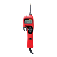
Removable
Probe Tip
Continuity Jack
& Rubber Cover
Speaker
Positive and
Negative
indicator lights
LCD
backlit
display
5 button
Navigation
“Hook” for
easy
hanging
Auxiliary Ground
Lead with a 4mm
gold plated jack
with 20A fuse.
START-UP ................................................................................................................................4-I
Operating Voltage Source .......................................................................................................4-I a
Connecting to the Vehicle’s Battery (Voltage Source) ............................................................4-I b
Y-Connector with Battery Clips ................................................................................................4-I c
Auxiliary Ground Lead ............................................................................................................4-I d
Flashlight .................................................................................................................................4-I e
Sleep Mode ..............................................................................................................................4-I f
FIVE BUTTON OPERATIONAL TERMS .....................................................................................5-II
PREFERENCES AND SETTINGS................................................................................................5-III
Preference Line .......................................................................................................................5-III a
Speaker ON/OFF .....................................................................................................................5-III b
Circuit Breaker Preferences .....................................................................................................5-III c
Power Switch Preferences .......................................................................................................6-III d
AC Threshold Preferences ........................................................................................................6-III e
LED Voltage Drop Preferences ................................................................................................6-III f
POWER PROBE HOOK MODE.... (the Smart Tip Advantage) ..................................................7-IV
Voltage Testing in Power Probe Hook Mode: .........................................................................7-IV a
Resistance Testing in Power Probe Hook Mode: .....................................................................7-IV b
Activating Components, Current Draw Testing and Calculated Resistance in Power Probe Hook Mode:..........8-IV c
Hot Shot
®
Testing in Power Probe Hook Mode: ....................................................................9-IV d
Dual Meter Feature: ...............................................................................................................9-IV e
CONTINUITY and RELAY TESTER ............................................................................................10-V
POWER PLUS MODE ...............................................................................................................11-VI
VOLT METER MODE ................................................................................................................11-VII
OHM METER MODE .................................................................................................................12-VIII
INJECTOR MODE .....................................................................................................................13 IX
COUNTER MODE ......................................................................................................................14-X
Duty Cycle Frequency .............................................................................................................14-X a
Positive Pulse Width/Frequency ............................................................................................14-X b
Negative Pulse Width/Frequency ..........................................................................................14-X c
Pulse Counter ........................................................................................................................14-X d
VOLTAGE REFERENCE SUPPLY MODE ....................................................................................15-XI
CONTRAST ...............................................................................................................................15-XII
SAVE PREFERENCES AND DEFAULT SETTINGS ......................................................................16-XIII
SAFETY ....................................................................................................................................17
FACTS AND TIPS .....................................................................................................................18
SPECIFICATIONS......................................................................................................................19
ENVIRONMENTAL ....................................................................................................................19
NOTES .....................................................................................................................................20 & 21
10 Gauge
Power Lead
Battery
voltage
Preferences
settings
4mm
banana jack
PPH1 Kit includes:
Power Probe Hook
3” Probe Tip
Battery hook-up clips
3 Wire Continuity Leads
Instruction manual
Table of Contents