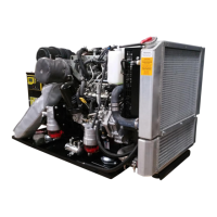
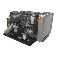
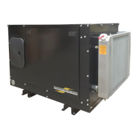
This document is the Operator's Manual for the Power Technology Southeast PTI-15/20-T4F generator set, powered by an industrial Isuzu diesel engine. It is part of Power Tech's Tier 4 Final Generator product line, engineered to high-quality standards for long, satisfactory service. The manual provides essential information for operating and maintaining the generator.
The generator set is designed to provide "Generating Power to the World." Its primary function is to convert mechanical energy from the diesel engine into electrical energy.
Important Technical Specifications:
- Engine Make: Isuzu
- Engine Model: 4LE2T
- EPA Tier: Tier 4 Final
- KWM @1800rpm: 30
- Oil Type: SAE 10W-40 (API Class)
- Oil Capacity: 8.4 Quarts (8 Liters)
- Cooling System Capacity: 11.25 Quarts (10.6 Liters) (for units with set-mounted radiator; capacities vary for remote radiator assemblies)
- Air Filter P/N: 04FA2768
- Primary Fuel Filter P/N: 08FF4LE-P
- Secondary Fuel Filter P/N: 08FF4LE-S
- OIL Filter P/N 15-20 KW: 01FO4LE
The generator is an exciter type, meaning it uses residual magnetism in the exciter pole pieces to induce voltage and initiate current flow in the exciter armature AC windings. This voltage is then rectified by a rotating rectifier assembly and fed to the alternator field, building up the generator's rated voltage. An Electronic Voltage Regulator (EVR), also known as an Automatic Voltage Regulator (AVR), maintains voltage accuracy at ±2% of the regulated voltage across the load range (no load to full load). The EVR rectifies part of the output voltage to provide DC voltage to the exciter field coils, controlling current flow and thus the exciter field strength. An adjustable rheostat allows for additional voltage adjustment.
Voltage Connection:
The generator can be connected at the terminal board to deliver 120/240 volts to a 3-wire grounded neutral system. For equipment requiring only 120-volts, the 120-volt connection is preferred as it allows the EVR to maintain voltage very close to 115 or 120 volts, regardless of power distribution. While 120/240-volt connection can be used for 110-volt loads, it may result in a high line-to-neutral voltage on the lightly loaded phase and a low line-to-neutral voltage on the heavily loaded phase, potentially affecting the starting of appliances like air conditioning and overloading the generator or tripping circuit breakers. For three-phase connections, Power Technology's Tech support department should be contacted.
Exciter Field Coil Voltage Source:
DC voltage for the field coil is obtained by rectifying voltage from the generator output's phase to neutral line or an appropriate terminal. The rectifier bridge is integrated into the static regulator, which senses changes in generator output and automatically adjusts current to the exciter field coil to regulate field strength.
Rotating Field Assembly (Rotor):
Comprises a shaft assembly, core assembly, field coil damper windings, and balance lugs. It is precision balanced for static and dynamic stability. Excessive overspeed should be avoided as it can damage rotor windings and field coils.
Core Assembly:
Consists of thin steel plates compressed and fastened together, with field windings wound around it.
Field Coil:
Made of heavily insulated wire, "wet" wound directly onto the poles. Leads are connected to the rectifier assembly for DC excitation voltage.
Bearing:
The generator rotor assembly is supported by a shielded, factory-lubricated ball bearing. Visual inspection for wear or leakage is recommended at service intervals, and replacement is necessary if issues are observed. Liquids should not be used to clean the generator end and bearing.
Stator Assembly:
Composed of steel laminations mounted in a rolled steel frame, with random wound stator coils fitted into insulated slots.
Usage Features:
The generator is operated via a PTG Series Controller, featuring an LCD display for viewing/changing settings and monitoring engine parameters.
- Front Panel Items:
- Off Button (O): Turns off the engine or exits Auto mode. Not an Emergency Stop.
- Auto Button (A): Places the controller in Auto mode, awaiting a start command.
- Run Button (I): Manually starts the engine. Requires the Off button to shut down.
- Up/Down Buttons: Navigate menus, change settings, or scroll parameter pages.
- Enter Button: Enters the menu, accepts settings, or locks/unlocks the LCD screen.
- Generator LED: Indicates engine status (Green = running, no issues; Amber = running, warnings; Red = shutdown, failure).
- Operating Modes:
- OFF: Engine cannot be remotely started.
- Auto: Engine waits for a start command.
- Running: Controller monitors engine parameters and waits for a stop command.
- Failure: Engine shuts down, displays reason. Requires reset with the Off button (except for Modbus).
- Menu: Allows changing settings and viewing event history (up to 150 events).
- Remote Panel Functionality: Enabled when the genset-mounted controller is in "AUTO" mode.
Maintenance Features:
The manual emphasizes safe operation and provides a detailed maintenance schedule.
- Daily Pre-Operational Checks:
- Engine oil level.
- Tightness and corrosion of battery cables/terminals.
- Coolant level.
- Absence of water in fuel.
- Absence of Diagnostic Trouble Codes (DTC) or failures.
- Absence of excessive fan belt looseness.
- Engine Maintenance Schedule: Includes daily, 150-hour, 500-hour, and 1000-hour intervals for various checks and replacements.
- Engine Oil: Change after the first 50 hours, then every 150 hours. Use SAE 10W-40 (API Class CJ-4) oil. Viscosity recommendations depend on ambient temperature (e.g., SAE 10W-30 or 15W-40 for temperatures above -10°C).
- Filters: Oil, primary fuel, secondary fuel, and air filters have specific replacement intervals (e.g., oil filter every 150 hours or once a year). Filter replacement intervals may vary based on air/fuel quality. The generator is equipped with filter minder capability to display filter change needs on the LCD screen.
- Coolant: Check level daily. Change every 1000 hours or once a year. Power Technology recommends a 1:1 mixture of water/glycol. Ethylene Glycol and Propylene Glycol are acceptable, with specific concentrations for freezing and boiling protection. Do not use Propylene Glycol in concentrations exceeding 50% due to reduced heat transfer.
- Hoses/Clamps: Replace fuel hoses and hose clamps every 2 years or earlier. Radiator hoses and clamps every 1000 hours or once a year.
- Belts: Check for damage, wear, or looseness daily. Replace every 1000 hours or two years.
- Cleaning Radiator Core: Visually inspect for obstructions and clean with running water. Avoid using hard objects. If equipped with remote radiator assemblies, remove the electric fan before cleaning.
- Operating Hours and Service Log: A log is provided to record operation hours and performed services.
The manual includes a "SAFE OPERATION" section with warnings and cautions.
- General Safety: Observe safety instructions, wear safety clothing (hardhat, eye protection, gloves), check the engine before operating, keep the area clean, handle fuel and lubricants safely, and be aware of exhaust gases.
- Burns and Battery Explosion: Be cautious of hot components. Do not remove the radiator cap while the engine is hot. Keep sparks and open flames away from the battery. Do not charge a frozen battery.
- Rotating Parts: Keep hands and body away from rotating parts (cooling fan, v-belts, pulleys, flywheel). Stop the engine before adjusting belt tension or checking the cooling fan. Do not run the engine without safety guards.
- Escaping Fluids: Relieve pressure before disconnecting lines. Do not check for pressure leaks with hands; use cardboard or wood. Seek medical attention if injured by escaping fluid.
- Anti-Freeze and Disposal of Fluids: Anti-freeze contains toxic chemicals; wear rubber gloves. Do not mix different types of anti-freeze. Dispose of fluids, filter cartridges, and batteries properly, consistent with environmental regulations. Do not pollute soil or water.
- Maintenance Safety: Ensure the engine is level and supported. Disconnect the battery before service. Stop the engine and remove the key for maintenance. Allow hot components to cool. Use appropriate tools. Use correct barring techniques for manual rotation. Perform service safely with multiple people. Keep a first aid kit and fire extinguisher handy.
Warranty:
Power Technology Southeast, Inc. warrants products to be free from defects in materials and workmanship. The warranty covers parts and labor for 2 years or 3000 hours (whichever comes first) from purchase, or 36 months from manufacture. Specific generator and engine parts are covered for 2 years or 3000 hours. Stand-by units are covered for 1 year or 1000 hours from installation, or 24 months from manufacture. Replacement parts are warranted for 30 days (excluding certain electronic components). Prior approval is required for warranty service. The warranty does not cover normal wear items, damage from accidents, abuse, improper servicing, unauthorized repairs, or use contrary to specifications. It is valid only within the contiguous United States and Canada.