EasyManua.ls Logo

PowerBass ATM 550.4 - User Manual

PowerBass ATM 550.4
24 pages
Print Icon
To Next Page IconTo Next Page
Loading...
ATM COMPACT CLASS A/B AMPLIFIER
Owners Manual
Please read through this manual to familiarize yourself with your new amplifier. Should your PowerBass
AutoSound mobile amplifier ever require service, you will need to have the original dated receipt.
ATM 330.2
ATM 440.2
ATM 550.4
ATM 660.4

Questions and Answers

  • M
    Michael BrownAug 8, 2025
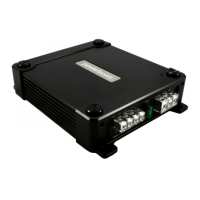
    What to do if the red status protection LED is ON and there is no output from my PowerBass ATM 550.4 Amplifier?
    • K
      Kevin HolderAug 8, 2025
      The red status protection LED indicates a problem that needs attention. Several issues could be the cause: * If the amplifier is very hot, the thermal protection may be engaged. Check the speaker terminals for proper impedance and ensure adequate airflow around the amplifier. * If the amplifier shuts down only when the vehicle is running, the voltage protection may be engaged. This means the voltage to the amplifier is outside the 10-16 VDC operating range. Have the battery/charging system inspected. * If the amplifier plays at a very low volume, the short circuit protection might be engaged. Inspect the speaker wires for shorts to each other or the vehicle's chassis. Also, using speakers with impedance below the minimum can trigger this.
  • M
    Melissa WrightAug 14, 2025
    Why is there alternator noise (varies with RPM) coming from my PowerBass Amplifier?
    • R
      Rickey ParkerAug 14, 2025
      Alternator noise that changes with RPM can be caused by several factors. Check for the following: * Damaged RCA cables * Improper routing of the RCA cables * A poor ground connection at the source unit * An amplifier gain setting that is too high (reduce the gain if it is) * A chassis ground short on the speakers
  • C
    Colleen StevensAug 20, 2025
    How to fix poor bass response on PowerBass Amplifier?
    • N
      Nicholas PowellAug 20, 2025
      To improve poor bass response, check the speaker polarity. Try reversing the connection of only one speaker.
  • S
    Sherry CamposAug 25, 2025
    What to do if the Power LED lights BLUE but there is no output from my PowerBass Amplifier?
    • Q
      qjohnsonAug 26, 2025
      If the power LED is blue but there's no output, try these steps: * Check the RCA connections. * Test the speaker outputs with a known good speaker. * Substitute a known good source unit. * Check for a signal on the RCA cable using a VOM (Volt Ohm Meter) in AC position.
  • E
    elizabethmillsSep 1, 2025
    How to troubleshoot a PowerBass ATM 550.4 when the power LED is not ON?
    • S
      sparksstephanieSep 1, 2025
      Using a Volt Ohm Meter (VOM), check the following: * +12 Volt power terminal (should read +12 to +16VDC) * Remote turn-on terminal (should read +12 to +16VDC) * Ground Terminal

Summary

Owners Manual Introduction

Model Identification

Lists the amplifier models covered by the manual.

Manual Purpose

Explains the manual's role in familiarizing users with the amplifier.

Welcome and Product Overview

Congratulations and Thanks

Expresses gratitude for the purchase and congratulates the user.

Key Product Features

Highlights engineering, testing, and construction of the amplifiers.

Safety Precautions: High Volume

Warns about potential hearing damage and traffic hazards from high volume.

Technical Features and Installation Preparation

Technical Features List

Details features like heatsink, inputs, crossovers, protection circuits, and cooling.

Installation Experience and Advice

Recommends professional installation and notes manual's general guidance.

Required Installation Tools

Lists essential tools needed for basic amplifier installation.

Installation Precautions and Mounting

General Installation Precautions

Outlines safety steps before and during installation.

Mounting the Amplifier

Stresses importance of location for proper cooling and access.

Mounting Location and Warnings

Optimal Mounting Location

Suggests suitable areas for mounting, considering airflow and protection.

Mounting Safety Warnings

Lists critical warnings against improper mounting locations and methods.

Control Panel Layout

Control Panel Diagram

Illustrates the layout of controls and their numbered positions.

Input and Gain Controls

Describes the function of line input jacks and gain adjustment.

Bass EQ and Crossover Controls

Explains the Bass EQ switch and the crossover adjustment controls.

Amplifier Connections and Indicators

Filter and Crossover Controls

Details the LPF, X-OVER switch, and HPF controls.

Power Status and Terminals

Describes the Power/Status LED and speaker output terminals.

Input Power and Ground Connections

Explains the BATT+, REM, and GND terminals.

Power Wiring and Signal Connections

Wiring Safety Warnings

Emphasizes disconnecting the battery and proper cable management.

Power Input Connection Diagram

Shows the recommended connection from the battery to the amplifier.

Power Wiring and Grounding Procedures

Voltage and Cable Gauge

Advises on checking voltage and selecting appropriate wire gauge.

Power Wiring Steps

Guides on connecting the power cable from the battery to the amplifier.

Grounding Best Practices

Details on finding and preparing a suitable chassis ground point.

Connecting Amplifier Terminals

Power and Ground Terminal Connection

Instructions on connecting power and ground cables securely to the amplifier.

Remote Trigger Wire Connection

Explains how to connect the remote turn-on lead for amplifier activation.

RCA Interconnect Wiring

RCA Wiring Diagram

Illustrates how to connect the amplifier using RCA interconnect cables.

RCA Cable Routing and Noise Prevention

Provides advice on routing RCA cables to avoid signal interference and noise.

High Level Connections (Optional)

High Level Input Functionality

Explains using high-level inputs for radios without RCA outputs.

Floating Ground Radio Wiring

Details connection for radios with a floating ground system.

Common Ground Radio Wiring

Details connection for radios with a common ground system.

4-Channel High Level Connections

4-Ch Floating Ground Wiring

Shows high-level connection for 4-channel models with floating ground radios.

4-Ch Common Ground Wiring

Shows high-level connection for 4-channel models with common ground radios.

Setup Adjustments

Input Gain Setting

Guides on adjusting the amplifier's input sensitivity for optimal sound.

Bass EQ Adjustment

Explains how to use the Bass EQ switch to boost bass frequencies.

High Pass Filter (HPF) Setting

Describes how to adjust the HPF crossover frequency for speaker systems.

Filter Settings and Speaker Wiring

Low Pass Filter (LPF) Adjustment

Guides on setting the LPF crossover frequency for subwoofer operation.

Speaker Load Requirements

Specifies the minimum impedance for stereo and mono operation.

Speaker Wiring Procedure

Details on connecting speaker wires, ensuring proper polarity and connection.

2-Channel Speaker Output Connections

2-Channel Full Range Connection

Illustrates connecting full-range speakers to the amplifier in 2-channel mode.

1-Channel Bridged Subwoofer Connection

Shows how to connect a subwoofer in bridged mode.

Bridging Load Caution

Warns about the minimum impedance requirement when bridging channels.

4-Channel Speaker Output Connections

4-Channel Speaker Configuration

Illustrates connecting speakers to the amplifier in 4-channel mode.

4-Channel Speaker Configurations

3-Channel Stereo;Mono Wiring

Shows configurations for using the amplifier in 3-channel setups.

2-Channel Bridged Subwoofer Wiring

Illustrates connecting subwoofers in 2-channel bridged mode for 4-channel amps.

Bridging Load Warning

Reiterates the caution for minimum impedance when bridging.

Wire Size Recommendations

Power Cable Selection Chart

Provides a chart for choosing the correct wire gauge based on fuse and length.

Personal Notes Section

Includes fields for users to record purchase and installation details.

Troubleshooting Common Issues

Power and Output Problems

Covers troubleshooting for power LED issues and lack of audio output.

Amplifier Performance Issues

Addresses common problems like overheating, shutdown, and low volume.

Audio Quality Issues

Guides on resolving alternator noise and poor bass response.

Amplifier Specifications

Two Channel Model Specs

Lists detailed technical specifications for the 2-channel models.

Four Channel Model Specs

Lists detailed technical specifications for the 4-channel models.

Specification Notes

Mentions that specifications are subject to change and warns against user repairs.

Limited Warranty Policy

Warranty Coverage Details

Outlines the one-year limited warranty for material and workmanship.

Warranty Exclusions

Lists conditions that void the warranty, such as damage or improper installation.

Service and Return Process

Explains the procedure for obtaining warranty service and returning products.

Company Information

Contact and Website

Provides company contact information, including address, phone, fax, and website.

PowerBass ATM 550.4 Specifications

General IconGeneral
BrandPowerBass
ModelATM 550.4
CategoryAmplifier
LanguageEnglish

Related product manuals