HOUR METER
This meter displays the values for engine total running time (in the
life of the generator). See MAINTENANCE section for application.
OPERATING THE GENERATOR
Failure to start and operate generator on a level surface can cause the unit
not to start or cause it to shut down unexpectedly during operation possibly
damaging appliances and other items connected to it.
Starter cord kickback (rapid retraction) can pull your hand and arm toward
generator engine faster than it can be let go of. Failure to be aware of this
function can result in broken bones, fractures, bruises and sprains can result.
STARTING THE ENGINE
1. For your protection, wear the protective safety glasses (Not provided).
2. Move the generator OUTSIDE in a fully VENTILATED area.
3. Place the generator on a FLAT and level surface and close to the working
surface. Keep a minimum of 1.5 meters CLEARANCE on all sides of the
engine including top. Face the engine exhaust outlet AWAY from dwellings.
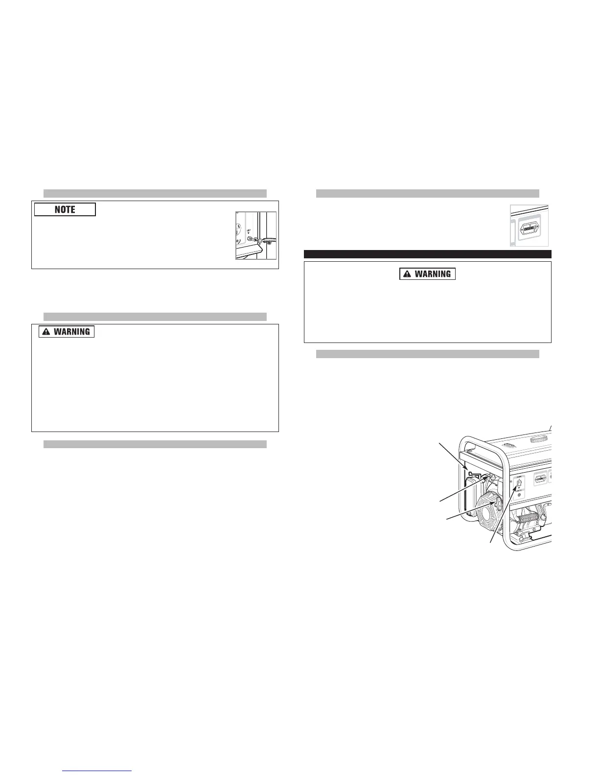
4. Turn the Petrol Valve lever counterclock-
wise to “ON” position to allow the
petrol to flow to the engine.
5. Slide the Choke Lever to “START”
(left) position.
6. Turn the Engine ON/OFF switch to ON
position.
7. To start the engine, pull Starter cord
slowly until resistance is felt, then pull
rapidly to avoid kick back. Repeat until
engine starts to run.
8. Slide the Choke Lever to “RUN”
(right) position.
SYSTEM GROUND
The Ground and Neutral pins in all AC outlets in this generator are BONDED (per-
manently connected) to the generator frame and its components.
See “CONNECTING TO A BUILDING’S ELECTRICAL SYSTEM” section for important
grounding information.
CONNECTING TO A BUILDING’S ELECTRICAL SYSTEM
Generator produces hazardous voltage. Failure to isolate
generator from power utility can result in serious injury or death to electric
utility workers due to backfeed of electrical energy. Do not connect the gener-
ator directly into your home's electrical system through a receptacle outlet.
Connections to a building’s electrical system for usage as standby power
must be provided by a qualified electrician. All connections must isolate
generator power from utility power or other alternative power sources and
must comply with all applicable laws and electrical codes.
When using generator for backup power, notify utility company. Use
approved transfer equipment to isolate generator from electric utility.
The Neutral Bond Wire (located inside the alternator of the generator) must be
removed when connecting this generator to a building electrical system.
1. Make sure engine is switched off.
Perform the following:
2. Remove the Alternator rear cover by removing its two mounting hardware.
3. Remove mounting hardware and remove the Neutral/Ground Bonding jumper
wire (Green/Yellow wire terminated by two ring lugs) which connects the terminal
block to the and body (chassis) of the alternator. Reinstall hardware and
tighten firmly.
4. Replace the alternator cover and its mounting hardware and tighten.
5. Peel off and remove “NEUTRAL BONDED TO FRAME” label on the front panel.
Store the label for future use.
6. When the generator is removed from the buildings electrical system the neutral
bond wire must be reconnected.
RU
OH RETEM
U
O
H RS
1
1
0
19 20
H
O
U
R
R
ETE
M
OH
U
RS
1
10
4
5 & 8
6
7
AC 240V/50Hz
THE FOLLOWING PROCEDURE MUST BE PERFORMED BY A REGISTERED ELECTRICIAN
Check the National Electrical Code requirements
for the frame and external electrical conductive partsof this
generator to be properlyconnected to an approved earth
ground. Local electrical codes may also require proper grounding
of the unit. For this purpose, a GROUNDING TERMINAL is
provided on the generator front panel.