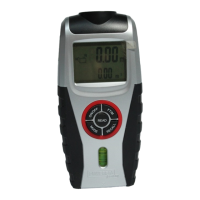
11 GB/CY
The air bubble of the level indicator should
be between the two markings
if the
alignment is horizontal.
Press the READ button
4
. The laser diode
11
projects a dot of light onto the end point of
the measurement. This dot of light will help you
to correctly align the ultrasonic rangefinder.
After successful measuring, the length will
appear in the display.
Avoiding measuring errors
In order to avoid measuring errors,
please note the following information:
The measurement is performed by ultrasound,
which travels from the ultrasonic transmitter
1
in a conical manner. The ultrasound is reflected
from the target area and received by the ul-
trasonic receiver. The ultrasonic rangefinder
calculates the measured length (Fig. B) from
the travel time of the signal.
In order to guarantee an exact measure-
ment, the following conditions must be
maintained (Fig. B):
The reference area (A) must be parallel to the
target area (B).
The distance to be measured must be be-
tween 0.6 m and 16 m long.
There must be no objects in the conical path
of the ultrasound, which could reflect the ul-
trasound prematurely. The conical path of the
ultrasound has a width of about 5 m at a
length of 16m.
The target area must have a smooth surface,
so that the ultrasound can be well reflected.