Be careful to assemble all components in the
sequence they are presented.
S T E P
9
Inch
MM
Note:
All Pulleys in this step are 4 1/4” diameter, except where noted in step 9B.
Leave all pulley bolts hand tight until step 10 is completed.
A. See Diagram 1. Insert small ball end of Low Pulley Cable (91) into the opening in Leg Extension Arm (K),
where pulley (B1) will be installed. Insert Cable (91) into and through Lower Main Frame (A). Run
Cable (91) along the top of the frame and into and through Lower Main Frame (A) again and pull entire
length of Cable (91) through.
B. See Diagram 2. Install 3 1/2” diameter Pulley (B1), over Cable (91) and into Leg Extension Arm (K) as
shown using:
One 52 (3/8” x 3 3/4” hex head bolt)
Two 14 (pulley spacer)
One 70 (3/8” nylon lock nut)
C. See Diagram 2. Install Pulley (B2), over Cable (91) and into Lower Main Frame (A) as shown using:
One 52 (3/8” x 3 3/4” hex head bolt)
Two 14 (pulley spacer)
One 70 (3/8” nylon lock nut)
D. See Diagram 2. Install Pulley (B3), under Cable (91) and into Lower Main Frame (A) as shown using:
One 52 (3/8” x 3 3/4” hex head bolt)
Two 14 (pulley spacer)
One 70 (3/8” nylon lock nut)
E. See Diagram 1. Route Cable (91) up through the opening in the Lower Main Frame (A).
See Diagram 2. Install Pulley (B4), over Cable (91) and into Lower Main Frame (A) as shown using:
One 52 (3/8” x 3 3/4” hex head bolt)
Two 14 (pulley spacer)
One 70 (3/8” nylon lock nut)
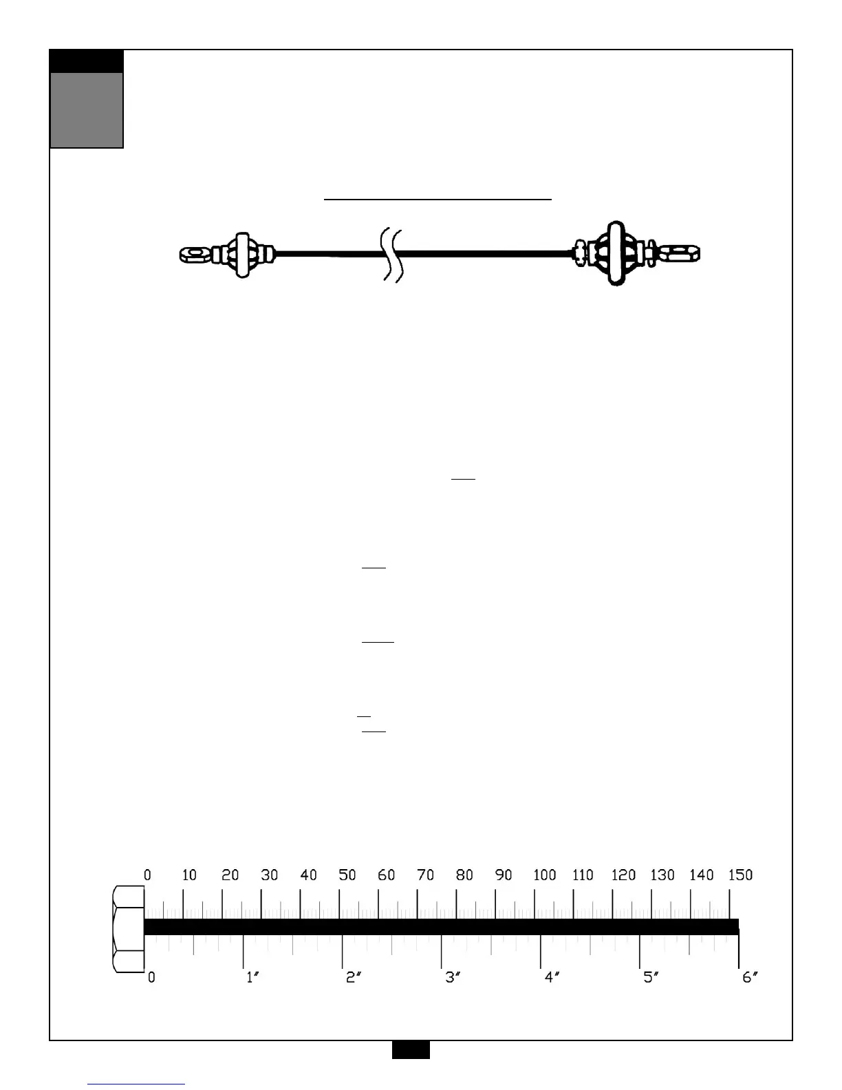
Low Pulley Cable (91)
Small Ball End
Ball Stop End
24
 Loading...