SETTING THE LIMIT SWITCHES
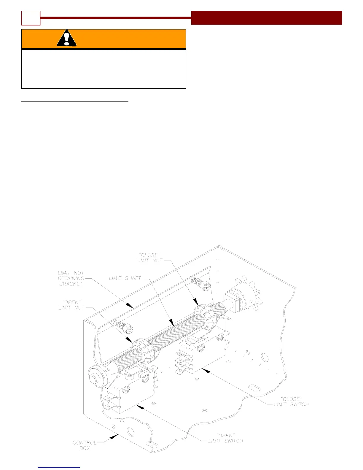
1. Open the cover on the electrical enclosure. There are two
limit nuts on the threaded shaft that move laterally along the
shaft as the operator opens and closes the door. When a limit
nut nears the end of the shaft it activates a (set of) switch(es).
The OPEN limit switch is on the LEFT and the CLOSE limit
switch is on the RIGHT. Auxiliary switches may also be
present, they are used to control other functions. These are
mounted to a separate bracket and should not be confused
with the the OPEN and CLOSE Limit Switches which are
mounted to the back of the electrical enclosure box and are
somewhat hidden from view.
2. Manually raise the door to a nearly open position.
3. Depress the limit nut retaining bracket away from the slots in
the limit nuts. Turn the OPEN limit nut on the shaft until it
TO AVOID RISK OF ENTRAPMENT AND POSSIBLE
DAMAGE TO THE DOOR AND OPERATOR THE LIMITS
MUST BE ADJUSTED BEFORE APPLYING POWER TO
THE OPERATOR.
WARNING
Figure 8
engages the Open Limit Switch, the switch will sound
an audible “click” when engaged. If the Open Limit is
a DPDT switch (a total of 6 (six) connecting terminals
protruding from the switch body, a SPDT switch has
only three (3) terminals), you will need to listen for two
audible clicks. Release the retaining bracket and be
sure that it engages in slots of both limit nuts.
4. Manually lower the door to a nearly closed position
and repeat Step #3 with the Close limit nut and
switch.
5. If auxiliary switches are present, the limit nut will
actuate them just prior to activating the open or close
limit switch. (This is preset at the factory.)
6. Manually move the door to a half open position to
avoid door damage due to incorrect power supply
phasing. On three phase units the door may initially
run in the wrong direction when power is first applied.
With the door in a mid position there will be time to
stop the door before damage can happen if incorrect
phasing occurs.
7. A final limit adjustment will be necessary after the
connection of the power supply in order to ensure the
door stops at the proper Open and Close positions.
10
INSTALLATION INSTRUCTIONS