19
ASSEMBLY INSTRUCTIONS
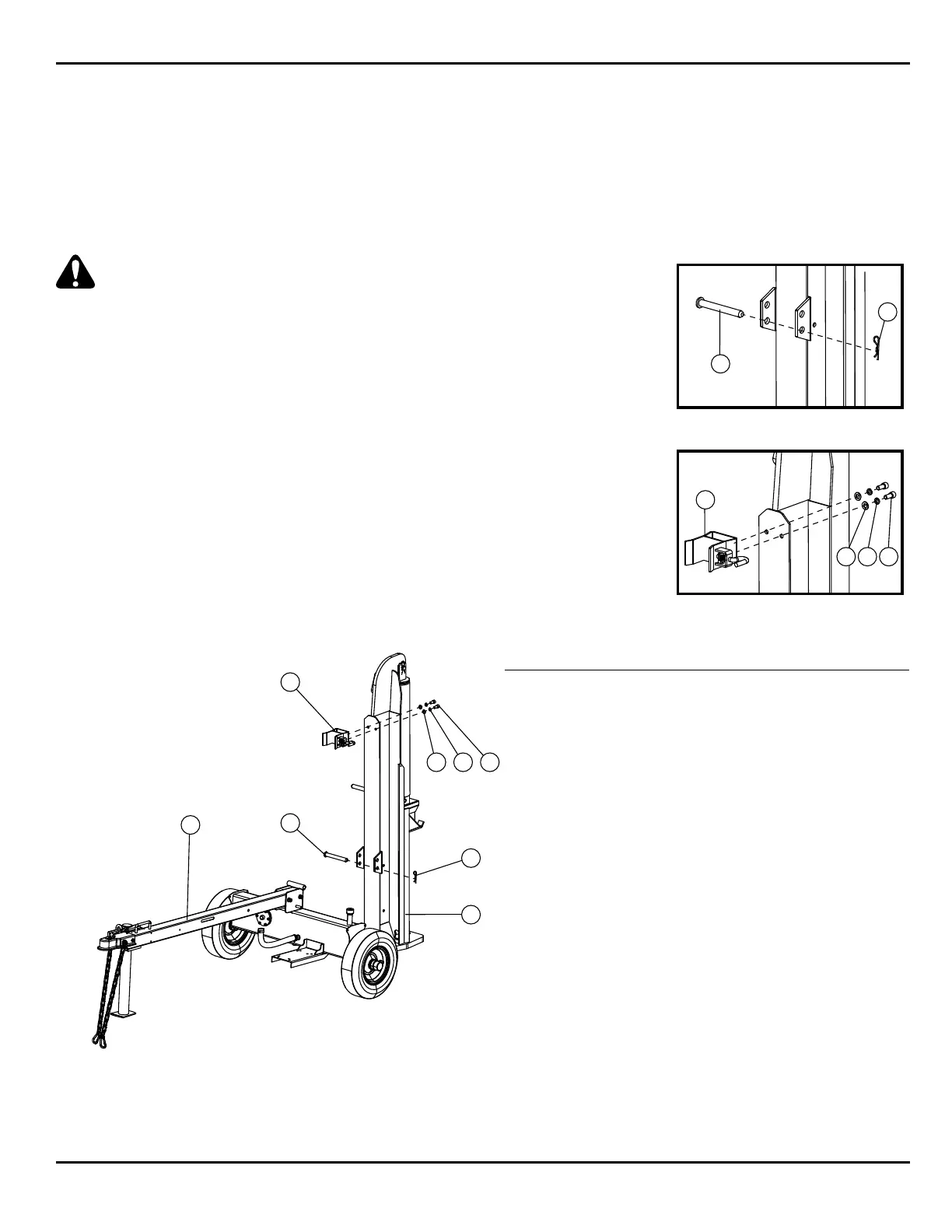
Step 4:
4a: Remove the two hold down bolts securing the beam to the crate base.
4b: Slide the beam down so that the foot plate hangs over the edge of the crate base.
4c: Using two people or a suitable lifting device, stand the beam assembly up on end
as shown, making sure that the beam is on a stable and level surface.
CAUTION: Have a person stabilize the beam until
it is secured to the tank/tongue assembly.
4d: Locate the pivot pin and r-clip from the hardware kit.
4e: Roll the tank/tongue assembly into position, aligning the pivot tube located on
the tank assembly with the holes located on the two tabs that are on the beam.
4f: Slide the pivot pin through both the holes and fasten with the R-clip.
4g: Engage the beam vertical lock located near the pivot tube on the tank assembly.
4h: With the beam in vertical position, locate the beam to tongue lock
(2) M12 x 25 SHCS, (2) M12 flat washers, and (2) M12 lock washers
from the hardware kit.
4i: Place the beam lock into position and align the holes.
4j: Fasten the beam lock in place using the provided hex wrench and hardware.
4k: Lower the beam into horizontal position and verify the beam locks
onto the tongue.
1
2
4
3
5
7 8 6
Item Description Quantity
1 Tank and Tongue Assembly 1
2 Beam Assembly 1
3 Pin 1
4 R-clip 1
5 Beam Lock 1
6 M12 x 25 Screw 2
7 Flat Washer 2
8 Lock Washer 2
4
3
4f:
5
7 8 6
4j: