21
ASSEMBLY INSTRUCTIONS
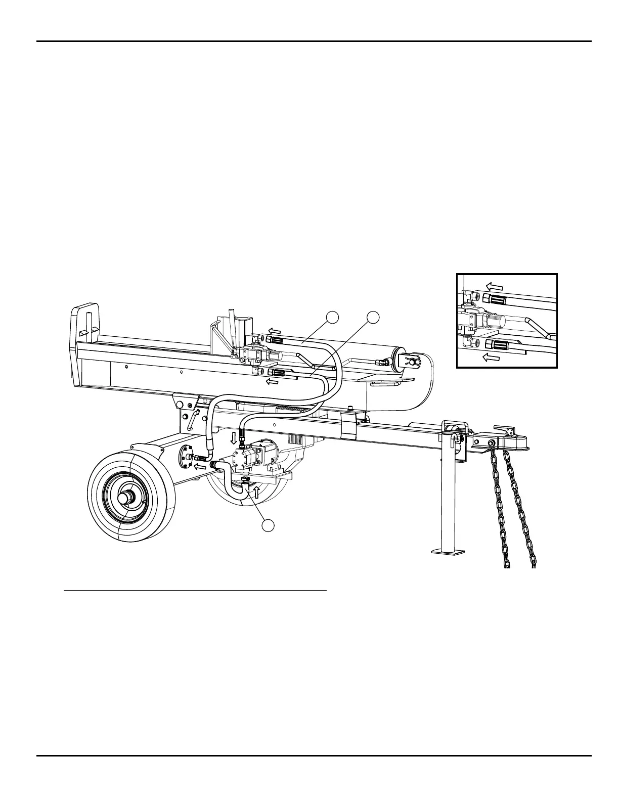
Step 6:
6a: Remove the plastic dust cap located in the end of the suction tube and loosen hose clamp.
6b: Slide hose onto the suction tube located on the bottom of the hydraulic pump and tighten clamp.
6c: Locate the two pressure hoses and remove the caps located in the ends.
6d: Take the hose with the 90 degree end and attach it to the round filter cover and tighten as shown.
6e: Attach the other end to the valve assembly as shown.
6f: Take the remaining hose and attach it to the pump and tighten as shown.
6g: Attach the other end to the valve assembly as shown.
Note: Hose connectors are designed to only fit on the proper connection and cannot be connected to the incorrect location.
2 3
1
Item Description Quantity
1 Suction Hose 1
2 Return Hose 1
3 Pressure Hose 1
 Loading...