Do you have a question about the powersoft Digam K4 and is the answer not in the manual?
Covers warnings for electric shock, fire hazards, and proper use.
Highlights essential safety rules like reading instructions and proper ventilation.
Lists compliance with Canadian Electrical Code, National Electrical Code, and European directives.
Alerts users about installation location, temperature, and humidity risks.
Details placement away from heat, proper ventilation, and avoiding liquids.
Emphasizes using grounded sockets, correct voltage, and not removing covers.
Warns about hazardous output voltages and touching exposed speaker wiring.
Explains high efficiency, sonic accuracy, digital reliability, and power factor correction.
Guides on carefully opening the carton and checking for shipping damage.
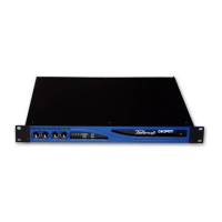
Details 19" rack mounting and the forced-air cooling system.
Advises on checking voltage, muting gain controls, and using quality cables.
Explains connection via CPC connector and the benefits of PFC.
Describes XLR and 1/4" jack input connections for analog signals.
Details Neutrik Speakon connector usage and bridge mode.
Explains RS485 data cable connection and ID selection for remote control.
Describes usage for emergency signals when 24V DC is applied.
Details relay outputs for external equipment and fault reporting.
Explains AES/EBU input mode and dedicated inputs on K3I/K2I models.
Introduces front panel controls and LCD display for amplifier management.
Describes the main screen display, including 'WAIT' and 'READY' statuses.
Explains scrolling menus, selecting options, and the menu tree structure.
Details setting output attenuation from 0 to -30dB for channels.
Covers setting gain levels (26-35dB) and corresponding sensitivities.
Explains choosing between Analog, Digital AS3, and Ethernet inputs.
Allows setting the maximum peak output voltage for channels.
Sets the maximum mains current limit, affecting circuit breaker trip.
Enables/disables clip limiters to prevent output distortion.
Mutes channels individually based on input signal amplitude thresholds.
Keeps amplifier muted at power on until manually deactivated.
Turns off output stage when no signal is detected for energy saving.
Configuration options available with an optional DSP board.
Configuration options available with an optional KAESOP board.
Selects LED bar function as output voltage or current meters.
Shows output signal values and load impedance for CH1 and CH2.
Displays historic temperature diagrams and current values.
Allows viewing the voltage and current of the mains supply.
Enables displaying the amplifier name and current preset name.
Stores and recalls amplifier configurations as local presets.
Displays serial number, hardware ID, and firmware versions.
Shows system parameters like power supply voltages and clocks.
Allows adjusting the contrast of the LCD display.
Enables setting a numeric code to lock/unlock settings.
Provides three levels of menu access restriction: All, Safe, and All.
Details that service activation is factory reserved.
Enables storing and recalling presets using a smartcard.
Explains the muting of amplifier outputs during power transitions.
Describes the system that protects output transistors from short circuits.
Details fan operation and automatic shutdown due to overheating.
Explains the protection circuit that cuts power supply for DC faults.
Mentions ultrasonic network for decoupling RF and stabilizing loads.
Provides instructions for cleaning the amplifier and removing dust filters.
Lists error codes and their descriptions displayed on the main screen.
Guides users on seeking qualified technical personnel for service.
Outlines warranty terms, conditions, and exclusions.
Directs users to local distributors or Powersoft for support.
Provides physical dimensions of the amplifier in millimeters and inches.
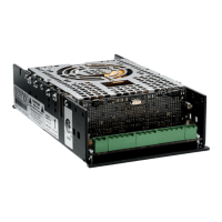
Illustrates the output stage and power supply block diagrams.
Lists detailed specifications for power, audio, and output parameters.
Shows peak output voltage settings for maximum output power.