4
ASSEMBLY
ASSEMBLY
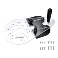
Refer to Figure 2–4
• Remove the adhesive backing from the right to left tape
measure and press into place. Start on the right end and
carefully place the tape along the front edge of the fence. Use
scissors to cut the excess tape from the left end.
• Attach the dust port to the back of the fence using the pan
head screws and 1/4” washers.
• From the front of the MDF adjustable fence faces, insert the
1/4"-20 x 1-1/2” screws through the MDF adjustable fence face
and fence, place a 1/4” washer over each screw and secure
in place with the round locking knobs. The MDF adjustable
fence faces can be adjusted left or right, after adjustment
has been made for the operation to be performed, tighten all
knobs securely.
• From the bottom of the fence insert the two 5/16"-18 x 1”
T-Bolts through the fence slot. Place a 5/16” washer and fence
locking knob on each T-Bolt. Place the fence onto the router
table and align the T-Bolts in the fence with the slots in the
router table. Tighten the knobs after adjusting the fence to the
operation being preformed.
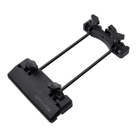
• From the back of the bit guard insert the two 1/4"-20 x 1”
T-Bolts, place 1/4" washers and round lock knobs on each
T-Bolt. Place the T-Bolts into the T-Slot on the face of the
fence and slide the bit guard onto the fence. NOTE: To
adjust the bit guard, loosen the knobs, slide the bit guard up
and down to desired application and tighten knobs. When
changing bits, slide the bit guard left or right of the opening.
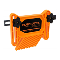
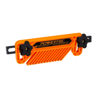
WARNING
To prevent kickback make sure the featherboard is at least 1”
(2.5 cm) from the saw blade.
• Place a spacer on each 5/16"-18 x 1-1/2" long T-Bolt and
insert through the slot in the featherboard, thread a round
locking knob on each T-Bolt and slide the T-Bolts into the
T-slot in the front of the fence. Position the featherboard(s)
and tighten locking knobs.
• Slide the T-Bolt on the flip stop into the T-Slot in top of the
fence, tighten the knob. The arm on the flip stop functions
as an easily adjustable stop and can be flipped up when not
needed. NOTE: The flip stop is multi-functional, please see flip
stop instructions for details. To prevent chip build up, the stop
does not extend the full width of the fence. However when
using a stop with material 3/8" thick or less, a longer stop
will need to be fabricated and can be mounted in the T-slot
located in the front of the fence.
IMPORTANT: Every routing operation is different, adjust the
various parts of the router fence and accessories as needed and
then tighten all knobs securely.
ADJUSTING THE FENCE FACES
Refer to Figure 5
The two MDF adjustable fence faces are designed to slide about
2" along the fence. This allows the opening for the router bit to be
adjusted from 0” up to 4".
Generally, the infeed and outfeed adjustable fence faces should
be adjusted as close to the bit as possible without contacting
the cutter. This will help prevent the ends of the workpiece from
drifting too far into the cutter at the beginning and end of the cut to
provide quality and safe cut.
Sometimes the “zero-clearance” support is needed to deliver an
even cleaner cut. In this case the router bit profile cuts into the
front edge of the infeed adjustable fence face so there is virtually
no gap between the cutter and the fence face. It delivers a cleaner
cut because the workpiece fibers are fully supported throughout
the cut.
If a zero clearance setting is necessary, follow these steps:
1. Set the bit height and fence position. Set both of the MDF
adjustable fence faces close to the bit without touching it,
the fence faces MUST NOT contact the bit at this time.
CAUTION
Set the bit guard directly over the router bit, at least 1/2” above
the top of the bit or the top of the workpiece (whichever is
highest), make sure the bit doesn’t cut into the bit guard.
2. Install, adjust and secure the bit guard.
3. On the back of the fence, slightly loosen the locking knobs
on the infeed MDF adjustable fence face. Start the router
and slowly slide the infeed MDF adjustable fence face into
the spinning router bit, stopping when the edge reaches
the bit’s guide bearing or midpoint (for bits that don’t have a
guide bearing).
4. Tighten the locking knobs on the back of the MDF
adjustable fence face to secure it in position.
 Loading...