EasyManua.ls Logo

PowerTec 71766 - User Manual

PowerTec 71766
4 pages
Print Icon
To Next Page IconTo Next Page
Loading...
INSTRUCTION SHEET
Precision Miter Gauge Fence System
UNPACKING CONTENTS
NOTE: Check for shipping damage. Check immediately whether
all parts and accessories are included.
ITEM DESCRIPTION QTY
A Miter Gauge
1
B
Telescoping Fence, 3" x 1-3/8" x 20"
with 12" Movable Scale
1
C 3" Fence Flip Stop with Pointer
1
D Extra Expansion Discs (Retain for future use)
4
E M4 Screws (for Expansion Discs)
4
F 5/16" Round Knobs
2
G T-Bolt 5/16"-18x3/4"
2
H 3 mm Hex Wrench
1
I 2.5 mm Hex Wrench
1
J Handle
1
K Washer for Handle
1
WARNING
For your own safety, read the machine's instruction manual before
using any accessory. Failure to heed these warnings may result in
serious personal injury and damage to the tool and theaccessory.
Before using the Precision Miter Gauge Fence System, read
and follow all instructions and safety information provided.
Always keep hands clear of the blade, cutter, sanding disc/belt.
Before making adjustments to the Precision Miter Gauge
Fence System, turn off the power, allow the blade, cutter or
sanding disc/belt to come to a complete stop and unplug
the machine.
Ensure handle and lock knob are tight beforeusing.
Before turning on the power afteradjustments, ALWAYS
verify there is a safe clearance between the blade and fence.
WARNING
Risk of accidental starting and serious personal injury.
Unplug the machine before attaching the Precision Miter Gauge
Fence System.
ASSEMBLY Refer to Figures 1, 2
NOTE: This miter gauge is equipped with a Locking Plunger
with spring loaded pin. The most commonly used angles are
notched with positive stops 0°, 15°, 22.5°, 30°, 45° and 60°.
To set or change the angles see TO USE on page 4.
Figure 1
See Figure 2. Place washer onto handle threads and thread the
handle onto the guide bar. Tighten handle.
Figure 2
Model No. 71766
23-0216
Question and Answer IconNeed help?

Do you have a question about the PowerTec 71766 and is the answer not in the manual?

Summary

Unpacking Contents

Assembly Instructions

Miter Gauge Setup and Adjustments

Setting the Gauge to 90 Degrees

Align the Miter Gauge Head and Indexer to 0° and verify perpendicularity to the miter bar.

Fitting to Miter Slot

Ensure the miter bar plate is tight or remove plate if not equipped with T-slotted miter slot.

Squaring the Miter Gauge Face

Adjust the screw to set the miter gauge face perpendicular to the table.

Fence and Flip Stop Installation

Installing the Fence

Expand or switch fence position by loosening knobs and pulling fence end.

Inserting the Flip Stop

Slide T-Bolt into fence slot, position arm, and tighten adjustment knob.

Features and Operation

Movable Scale Features

Utilize the 12" movable scale with pointer for accurate measurements and workpiece length setting.

Calibrating the Scale

Align the 0 mark of the scale to the pointer using the flip stop.

Setting Angles

Use the adjustment plunger and protractor scale to set precise angles.

General Usage Instructions

Unlock the adjustment plunger to move the miter gauge freely side-to-side.

Safety Warnings and Precautions

Overview

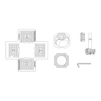
The POWERTEC Precision Miter Gauge Fence System, Model No. 71766, is an accessory designed to enhance the accuracy and versatility of miter cuts on various woodworking machines. This system is engineered to provide precise angle adjustments and workpiece support, making it suitable for a range of cutting tasks.

Function Description:

The primary function of the Precision Miter Gauge Fence System is to guide a workpiece at a precise angle relative to a cutting blade, cutter, or sanding disc/belt. It consists of a miter gauge head, a telescoping fence with a movable scale, and a fence flip stop. The miter gauge head allows for angle adjustments, including positive stops at common angles like 0°, 15°, 22.5°, 30°, 45°, and 60°. The telescoping fence provides extended support for longer workpieces and features a movable scale for accurate length measurements. The fence flip stop allows for repeatable cuts at specific lengths. The system is designed to fit into standard miter slots on saw tables and can be adjusted for side movement to ensure a snug, free-sliding fit. It can be used as a conventional miter gauge or with the included fence for enhanced functionality.

Important Technical Specifications:

  • Miter Gauge Head: Equipped with a Locking Plunger with a spring-loaded pin for positive stops at 0°, 15°, 22.5°, 30°, 45°, and 60°. The protractor scale on the miter gauge head acts like a Vernier scale, allowing for precise angle settings beyond the positive stops.
  • Telescoping Fence: Measures 3" x 1-3/8" x 20" with a 12" movable scale. It can be extended with an I-Beam Extender and a 3" Fence End to achieve a maximum extension of 34".
  • Fence Flip Stop: Features a pointer for accurate length calibration and an arm designed to accommodate a 3/4" sacrificial board without requiring conversion or adjustment. The flip stop arm can be positioned to either the left or right side of the body.
  • Adjustment Mechanisms: Includes a 3 mm hex wrench for adjusting miter head screws and miter bar plate screws, and a 2.5 mm hex wrench for adjusting expansion disc screws.
  • Miter Bar: Features an adjustment screw to set the miter gauge face perpendicular to the table.
  • Knobs and Bolts: Utilizes 5/16" Round Knobs, T-Bolts (5/16"-18x3/4"), and Fence Lock Knobs for securing components.
  • Materials: Components are designed for durability and precision, with careful consideration for materials that will not be damaged by common shop chemicals if proper cleaning procedures are followed.

Usage Features:

  • Angle Setting: The miter gauge head can be set to precise angles using the locking plunger for positive stops or by fine-tuning with the Vernier-like scale. To set a desired angle, the handle is loosened, the adjustment plunger is pulled and twisted counter-clockwise to unlock, allowing free movement. For positive stops, the plunger is twisted clockwise to engage the desired notch. For non-positive stops, the handle is tightened once the desired angle is achieved.
  • Fence Extension: The telescoping fence can be expanded by loosening the fence lock knobs and pulling out the 3" Fence End to the desired length. The I-Beam Extender provides an additional 17" of extension, allowing for a total maximum extension of 34". The I-Beam Extender can be used on either end of the fence.
  • Flip Stop Functionality: The fence flip stop slides into the T-slot on the top of the fence or 3" Fence End. Its pointer is used to calibrate the movable scale for accurate workpiece length measurements. The unique cylindrical shape of the flip stop's body wedges into the T-track, eliminating slack and movement. The flip stop arm's design allows for the use of a sacrificial board without needing adjustments. The arm can be repositioned to the left or right by removing a bolt and reassembling.
  • Miter Slot Fit Adjustment: The miter bar features expansion discs that can be adjusted with a 2.5 mm hex wrench to remove side movement in the miter slot, ensuring the bar slides freely without play.
  • Perpendicularity Adjustment: The miter gauge face can be squared to the miter bar by loosening screws on the miter head and bottom face, using a square to set perpendicularity, and then re-tightening. The miter bar also has an adjustment screw to set the miter gauge face perpendicular to the table.
  • Scale Calibration: The 12" movable scale on the fence is calibrated by setting the fence a safe distance from the blade, placing the right side of the flip stop to the left side set tooth, and aligning the 0 mark of the scale to the pointer.
  • Safety Features: Warnings emphasize reading the machine's instruction manual, keeping hands clear of the blade, unplugging the machine before adjustments, ensuring handle and lock knob tightness, and verifying blade clearance. The adjustment plunger should always be in the UNLOCKED position when moving the set pin to avoid damage.

Maintenance Features:

  • Cleaning: The system should be kept dry, clean, and free from oil and grease. A clean cloth should be used for cleaning. Avoid using brake fluids, gasoline, petroleum-based products, or strong solvents, as these can damage, weaken, or destroy plastic components, potentially leading to serious personal injury.
  • Part Replacement: When servicing, only identical replacement parts should be used to ensure safety, reliability, and prevent product damage. All repairs should be performed by a qualified service technician.
  • Wrench Inclusion: The system includes 3 mm and 2.5 mm hex wrenches for various adjustments, facilitating easy maintenance and setup.
  • Expansion Discs: Extra expansion discs are provided for future use, indicating a design that anticipates potential wear or loss of these small but critical components.

PowerTec 71766 Specifications

General IconGeneral
BrandPowerTec
Model71766
CategoryPower Tool
LanguageEnglish

Related product manuals