MOUNTING
To mount
the windlas.s,
refer
1o
Figure
1 and
follow lhe
procedures
oullined
below.
Tools Requir€d:
.
Electric
drill and'112",1-1l8'and
2" drill bits
.
Terminal
crimping
lool
.
Adiustable
wrench
.
Flathead
screwdriver No.2
Meterial Requircd
(not
included):
.
3/8"-16
bohs
(4
€tainless steel) Bolt length depends
upon deck thickness.
Calculate the deck thickness
and add an additional
1-1l4' length forthe
overallboft
length. Exatnple:
1-112"
deck + 1-114'
clearance
=2-34'
boh length.
.
98' diameterflat
and lock washers
(4
stainless
sleel)
.
Marine
plywood
(optional)
for underdeck
support back
olate
.
#8 wood screws
(4)forlhe
switch mounting
plate
(Bolt
length depends
upon mounting localion)
.
Anchor
.
Batlery
terminal
(2)
.
#2
gauge
wire
-
red
-
battery
to control unit
.
#2
gauge
wire
-
black
-
battery to control
unit
.
{f2
gauge
lugs
(6)
.
#16
gauge
wi.e
-
blue
-
switch to conlrol
unit
.
#16
gauge
wire
-
green
-
swilch
to
control unit
.
#16
gauge
wire
-
white
-
switch to control unit
.
#16 wood scfews
(4)
-
control unit
.
5/16'-18 x |' Hex head
screw
(1)
--t
Circuit
.
s/t6" lock washer
(1)
|
breaker
.
5/16'nut
(1)
-
connections
MOUNTING
HOLES
CHAIN/ROPE
LOCKER
HOLE
Figure 1 Mounting And
Wring Hole Locations
1 . Place lhe enclosed template in the desired
posi-
lion
on lhe
deckand tape into
position.
Besurethe
centerline of thetemolale is on the centerline
of the
bow
IMPORTANT: Be
absoluteV
certain
that
the windlass is
installed
over
the
rope/chain locker before
drilling any
mounting holes. The
anchor
rope will feed into the rope
locker through a lwo inch hole in the deck of the boat.
2.
Spot and
drill
the
holes as shown on the template.
Fhere arelour 1/2'mounting holes, one 1-118"
hole
for the wiring harness and
one 2' hole forlhe rope/
chain hole tothe locker
(See
Figure l and/or mount-
ing template). lf using the optional marine
plywood
base undemeath, usethe same mounling
template
lor
hole locations.
3.
Placethe windlass in
oosition
and
boll the windlass
to the deck
using 31i8"-16 bolts, lock washers
and
f lat washer.
CONTROL UNIT INSTALLATION
To install
control unit,
refer to Figure 2 and follow the
outlined orocedures.
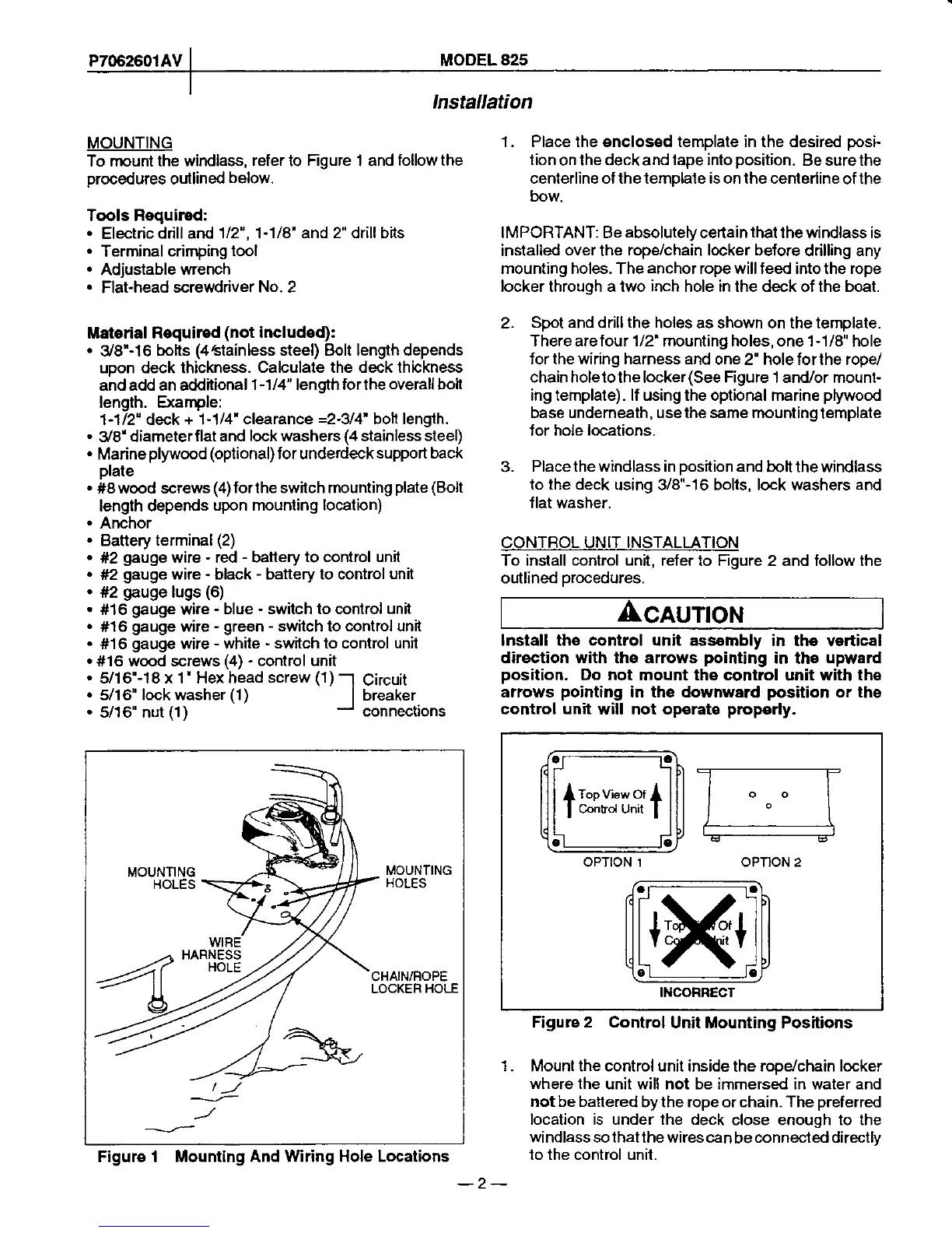
CAUTION
lnstall the control unit assombly
in the vertical
direction with ths arrows
pointing
in ths
uprvard
position.
Do not mount the control
unit
with th6
arrows
pointing
in the downward
position
or the
control
unit
will not operate
proporly.
Figure 2 Control
Unit Mounting Positions
1 . Mount the control unit inside
the
rooey'chain locker
where the
unit will not be immersed in waler and
not be battered
by the rope or chain- The
preferred
location is under the deck
close enough to the
windlass sothatthe wires can
be
connected directlv
lo the control unit.
a
c
tm*umt
c
c
OPTION 1 OPTION 2
a a
c
c
INCOFRECT
-2-
 Loading...