lnsta I lati
o n
(C
onti n ued
)
lf
possible,
mount the control
unit
verlically shown
in Figure
2
-
Option 1. Nev€r mount the control
unit
with the arrow
pointing
in the downward
position
or
the unit will not operate
properly.
Horizontal rnount-
ing
is
acceptable, but not
preferred
(Option
2).
Drill lhe mounting holes
using the conlrol
unit as a
lemplate.
Fasten the control unit with tour #16 wood screws.
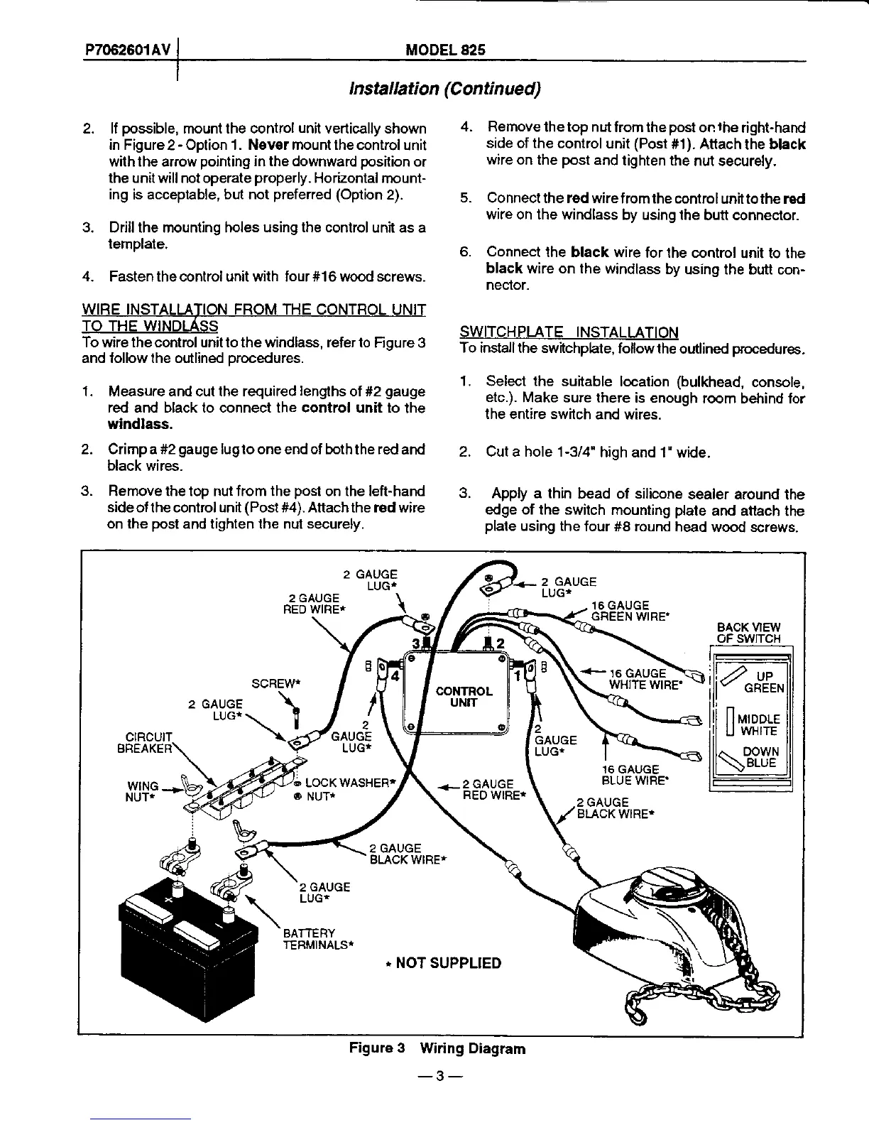
To wire lhe control unil to lhe windlass, refer to
Figure 3
and lollow the outlined orocedures.
'1.
Measure and cut lhe required
lengths
of #2
gauge
red and black to connect the control unit to the
windlass.
2. Crimp a #2
gauge
lugto one end of boththe red
and
black wires.
3.
Remove lhe top nut from the
post
on lhe left-hand
sideoflhe control unit
(Post#4).
Attachthe red wire
on
lhe
post
and lighten lhe nut
securely.
Remove
thetop nut
from the
post
on
lhe
right-hand
side of the control
unil
(Post
#1). Atlach
the
black
wire
on the
post
and
tighten the
nut securely.
Connect the red wirefromthe
controlunit
tothe red
wire on the windlass
by using the
butt conneclor.
Connect
lhe black wire
for lhe control
unit to the
black
wire on the windlass
by
using the butt con-
neclor.
SWITCHPLATE INSTALLATION
To install the switchphte,
follow the
outlined
procedures.
1. Select the suitable
location
(bulkhead,
console,
etc.).
Make sure lhere
is enough
room behind lor
the entire switch
and wires.
2. Cut a hole 1-3/4"
high and 1"
witJe.
3.
Apply a lhin
bead of silicone
sealer around
the
edge of the switch
mounting
plate
and
attach lhe
plale
using the
four #8 round
head wood screws.
4.
o.
4.
LUGT
2
GAUGE
LUG*
2 GAUGE
RED
WIRE*
16 GAUGE
GREEN
WIRE'
BACK VIEW
oF swtTcH
SCREW*
2 GAUGE
LUG*
CIRCUIT
BREAKER
WING
NUT*
16 GAUGE
BLUE WIRE'
BLACK
WIRE*
BLACK WIRE*
2
GAUGE
LUG*
BATTERY
TERMINALST
-
NOT SUPPLIED
Figure 3
Wiring Diagram
-3-