P70626014V
lnstallation
WIRE INSTALLATION
FROM THE SWITCH
TO
THE
CONTHOL
UNIT
To wire the switch lo the controlunil. referto Fioure3 and
follow the outlined
procedures.
1 . Measure and cul the required
lengths
of #16
gauge
green,
while and blue wires to connect the switch
to the contrcl unit.
2. Connect lhe #16
gauge green
wire to the
grcen
wire on
lhe co?trol
unit and
the
green
wire on the
swilch using butt conneclors.
3. Connect the#16
gauge
white wire to the white wire
on
lhe
control unit and the white
wire on
lhe
switch
using butt connectors.
3.
Connecl
the #16
gauge
blue
wire to the blue wire
on the control unil and the blue wire
on the
switch
using bun conneclors.
WIBE INSTALLATION FROM THE CONTFOL
UNIT
TO THE BATTERY
To wire the contfol unit to the battery, reier to Figure 3
and
follow the
outlined
procedures.
1 .
Measure and cut the required
lengths
ol
#2
gauge
red and black wires to connecl the control unit to
the
banory.
2. Crimp a lf2
gauge
lug to all four ends of the wires.
CAUTION
Never
attach tho circuit
breaker to the battery
ground
terminal
(negative
G)
post).
3. Attach the circuit breaker to the
positive
(+)
side of
the battery.
4. Attach one end ofthe redwirelothe other end ofthe
circuit breaker
by using a 5/16'-18 x 1' hex head
screw with a 5/16' lock washer and
nut.
5. Remove the top nut from the
post
located to the left
of the
green,
white and blue wires used to connecl
the swilch to the control unit
(Post
#3). Attach the
red wire on the
post
and
tighten
the
nut
securely.
Never attach the black wire
to
the battery
hot
ter-
minal
(positive (+)
post).
6.
Attach the black wire lo the negative
O
side of the
batterv.
CAUTION
Awnnxrue
MODEL
825
(Continued)
7. Rernove the top
nut
lrom
the
post
located to
the right
ofthe
green,
whiteard bluewires used
lo connecl lhe
switch to the
control unit
(Pos{
tt2).
Attach lhe black
wire on the
post
and
tighlen the nut securely.
RODE INSTALLATION
The wirdlass is
designed to accepl anchor line,
chain or
a combination olthe
two. Howaner.
it is imoortanl that the
rope-to-chain
splice be done conea!.
A
shaclde
will
not
fit
through
the chain
gypsy.
The warranty
is invalilated if
a shaclde
is used. Use an eye splbe
to atlach the anchor
chain lo the rope. This
prrcedure
should be done
by
a
prolessional
at a
rnarina. However, complete
rope splic-
ing
instnrclion
are availablein Chapnan
Pibting S@rnan-
ship and Snma
B@t Handling, Chales
E. Clraprnan.
Use 916"
or U8" Acc@
proof
coil
chain or 1/2" or
5/8" Powerwinch line
only. Run the chain through
the windlass before splicing
to ensure
there is an
exact match
between the chain
and the
gypsy,
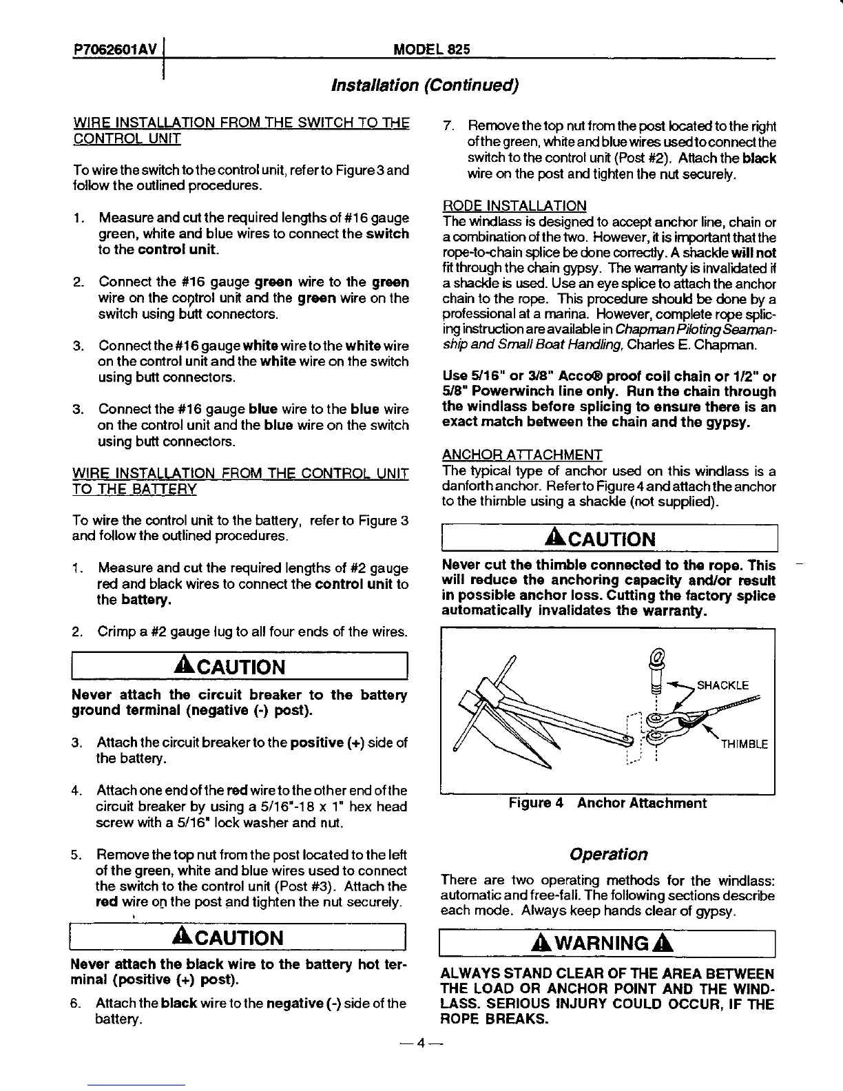
ANCHOR
ATTACHMENT
The typical
type
of
anchor used on lhis
windlass is a
danforth anchor. Referto
Figure 4 and attachthe
anchor
to the thimble
using a shackle
(not
supplied).
CAUTION
Never cut the thimble
connocted to th€
rope. This
will r€dsce
the anchoring capacity
and/or rosull
in
possibl€
anchor loss. Cutting
the lactory
splice
automatically invalidates the
warranty.
tg
U
i
SHACKLE
TH IM 8LE
Figure 4 Anchor Attachment
Operation
There are two operating
methods for
the windlass:
automalic
andfree{all. The following
sections describe
each
mode. Always keep hands clear
of
gypsy.
ALWAYS STAND CLEAR OF THE
AREA BETWEEN
THE
LOAD
OR
ANCHOR POINT AND
THE WIND.
LASS, SERIOUS INJURY COULD
OCCUR. IF
THE
ROPE
BREAKS.
-4-
 Loading...