7
2. Introduction
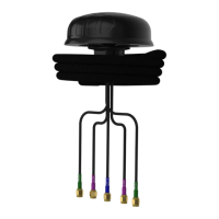
This User Guide provides information on the
installation instructions for the omni-directional
antenna (PUCK-V2 Series).
Antenna Configuration 1
Threaded Spigot Mounting
Use the Drill template below or download the 1:1
drill template from
http://www.poynting.tech/downloads.
• Choose the mounting location carefully and a
position at least 50cm from heat sources, with
a clear line of sight to the sky.
• Once you have decided on the location and
checked that there are no obstructions such as
cables or channels below the mounting
surface, for the fastening nut and cables to
pass through, use the downloaded 1:1 drill
template to mark the mounting location.
• To prevent the marking tool or drill from sliding
off course, use masking tape over the drilling
point to help hold the drill point in place. The
masking tape also prevents hot shavings from
the drill or hole saw which could penetrate and
damage the painted surface.
• Clean the entire surface on which you plan to
mount the antenna. Cleaning is done so as not
to damage the vehicle’s paint and to ensure
good contact of the foam surface to the
mounting area.
• Alcohol wipes can be used to remove oil and
dirt from the surface.
• The 35mm threaded Spigot should be used to
secure the antenna to a surface structure of
20mm thickness or less. Likewise, the 75mm
threaded Spigot should be used to secure the
antenna to a surface structure of 60mm
thickness or less.
 Loading...