Do you have a question about the PPI Neuro 102EX and is the answer not in the manual?
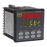
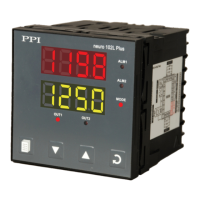
Explains the function of the Upper and Lower LED Readouts on the controller's front panel.
Details the function of the 9 LED indicators on the controller's front panel.
Explains the function of the eight tactile keys on the controller's front panel.
Covers controller power-up sequence, main display, and % output power indication.
Details how to adjust the Control Setpoint (SP) and indicates the Tuning mode status.
Explains how to operate the controller in Manual Mode, including activation and adjustments.
Describes the Standby mode for 'indication-only' operation with outputs off.
Introduces the Operator Page for frequently adjusted parameters.
Describes Operator Commands for Profile and Standby modes, accessed via the CMD key.
Explains how to enter and navigate the Set-up Mode to view and modify parameters.
Details the Master Lock feature to restrict parameter adjustments for security.
Lists and describes parameters for PID, On-Off, and Pulsed On-Off control algorithms.
Covers configuration for Alarm-1, including type, setpoint, deviation band, and hysteresis.
Covers configuration for Alarm-2, including type, setpoint, deviation band, and hysteresis.
Details parameters for input type, PV resolution, units, and input ranges.
Describes parameters for PV range, setpoint limits, offset, and digital filter for DC linear inputs.
Lists various input types supported by the controller, including thermocouples, RTDs, and DC signals.
Lists parameters for controlling tuning, overshoot, auxiliary setpoint, and recorder output.
Details supervisory control over manual mode, alarms, standby, profile abort, and communication settings.
Explains configuration for profile segments, cycles, output status, and power fail recovery.
Covers setting individual profile segments: Target Setpoint, Time Interval, Holdback.
Explains viewing profile status and on-line alteration of parameters for the current segment.
Describes commands to start, abort, pause, or skip profile segments.
Details the function selection and type configuration for Output-2.
Covers parameters for Output-3 (Alarm/Recorder), Output-4 (Alarm), and Output-5 (PV/SP Retransmission).
Lists parameters for implementing custom linearisation curves for DC linear inputs.
Describes the controller's basic electronic assembly and its removal from the enclosure.
Explains jumper configurations for selecting input types on the CPU PCB.
Details jumper settings for configuring Output-1 type (Relay, SSR, DC Linear).
Describes the types of plug-in modules available for outputs OP2, OP3, OP4, and OP5.
Describes the DC Linear Voltage and Current Modules and their configuration.
Explains the mounting of the Serial Communication Module on the CPU PCB.
Shows controller dimensions and specifies panel cutout requirements and minimum spacing.
Provides step-by-step instructions for securely mounting the controller on a panel.
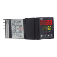
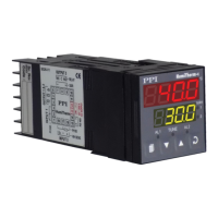
Provides wiring diagrams and descriptions for power supply, inputs, outputs, and serial communication.
Explains power supply connections and safety precautions for line supply.
Explains the function and connection of digital inputs for auxiliary SP selection and profile start command.
Lists Modbus communication addresses, supported functions, and notes on data interpretation.
| Brand | PPI |
|---|---|
| Model | Neuro 102EX |
| Category | Controller |
| Language | English |