Do you have a question about the PPI FLOREX and is the answer not in the manual?
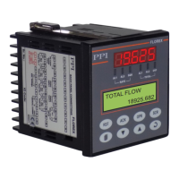
Describes the digital displays on the front panel, including the Upper Readout and Lower Readout.
Details the six front panel LED indicators and their associated statuses for flow rate and total status.
Lists and describes the eight tactile keys on the front panel and their associated functions.
Describes the default screen displayed after power-up, showing measured Flow Rate and accumulated Flow Total.
Outlines the recommended sequence of parameter settings for initial instrument setup.
Explains how the totaliser mode is used to monitor accumulated Flow Total and how to reset it.
Describes how to configure and operate the FLOREX in Batch Control mode for managing batches.
Explains how to enter and navigate the program mode to view or modify parameter values.
Details the procedure for adjusting parameter values using the front panel keys.
Describes parameters that are presented to the user only if certain conditions are met.
Explains how to enable or disable parameter locking for security and preventing unauthorized changes.
Covers Alarm-1 type, setpoint, hysteresis, inhibit, logic, and latch settings.
Covers Alarm-2 type, setpoint, hysteresis, inhibit, logic, and latch settings.
Details parameters for enabling Total Alarm-1 and its set point, extension set point, logic, and time.
Details parameters for enabling Total Alarm-2 and its set point, extension set point, logic, and time.
Configures the output type (mA, V) and the low/high range for the retransmission signal.
Selects the input type (e.g., mA, V) and the time base for flow accumulation.
Sets display resolution and PV ranges (low/high) for input scaling.
Covers filter constant, scale activation, minimum/maximum values, and square root function.
Grants supervisory permission for adjusting alarm setpoints on the Operator Page.
Controls the activation or de-activation of the Minimum & Maximum Flow Rate value storage feature.
Configures baud rate, parity, and serial ID for master device communication.
Controls whether parameters can be altered via serial communication.
Allows the user to lock or unlock parameter value adjustments for security.
Resets all user-settable parameters to their factory default values.
Accesses Factory Calibration Regain and User Calibration for Analog Input.
Facilitates linearization of the Analog Input curve based on user-derived values.
Enables or disables the user linearization function for the flow rate indication.
Configures total points and actual/derived points for user-defined linearization curves.
Describes the internal electronic assembly comprising printed circuit boards (PCBs).
Covers jumper settings for both input and output configurations on respective PCBs.
Describes types of plug-in modules for outputs (Relay/SSR, DC Linear Voltage/Current) and serial communication.
Lists precautions to be observed during indicator installation for optimal operation and safety.
Provides step-by-step instructions for mounting the indicator on a panel.
Highlights critical safety warnings regarding electrical connections and potential hazards.
Details how to connect DC Linear Current/Voltage (mV,V,mA) input signals from flowmeters.
Explains connections for Output-1, Output-2, Output-3, and Output-4 (Relay/SSR/Voltage/Current).
Describes connections for AC/DC power supply and the serial communication port.
| Brand | PPI |
|---|---|
| Model | FLOREX |
| Category | Controller |
| Language | English |