Removing Assembly from Enclosure
Hold the indicator upside down and press the pullout latch to unlock the front bezel from the enclosure (Refer Figure 12.2
above). Pull the bezel outward. The electronics assembly comes out with the bezel.
Placing Assembly Back into Enclosure
Hold the Enclosure and the Bezel such that the Latching Slot on the Enclosure and the Pullout Latch on the Bezel face upward
(See Figure 12.2). Insert the bezel gently into the Enclosure until the Bezel snap fits.
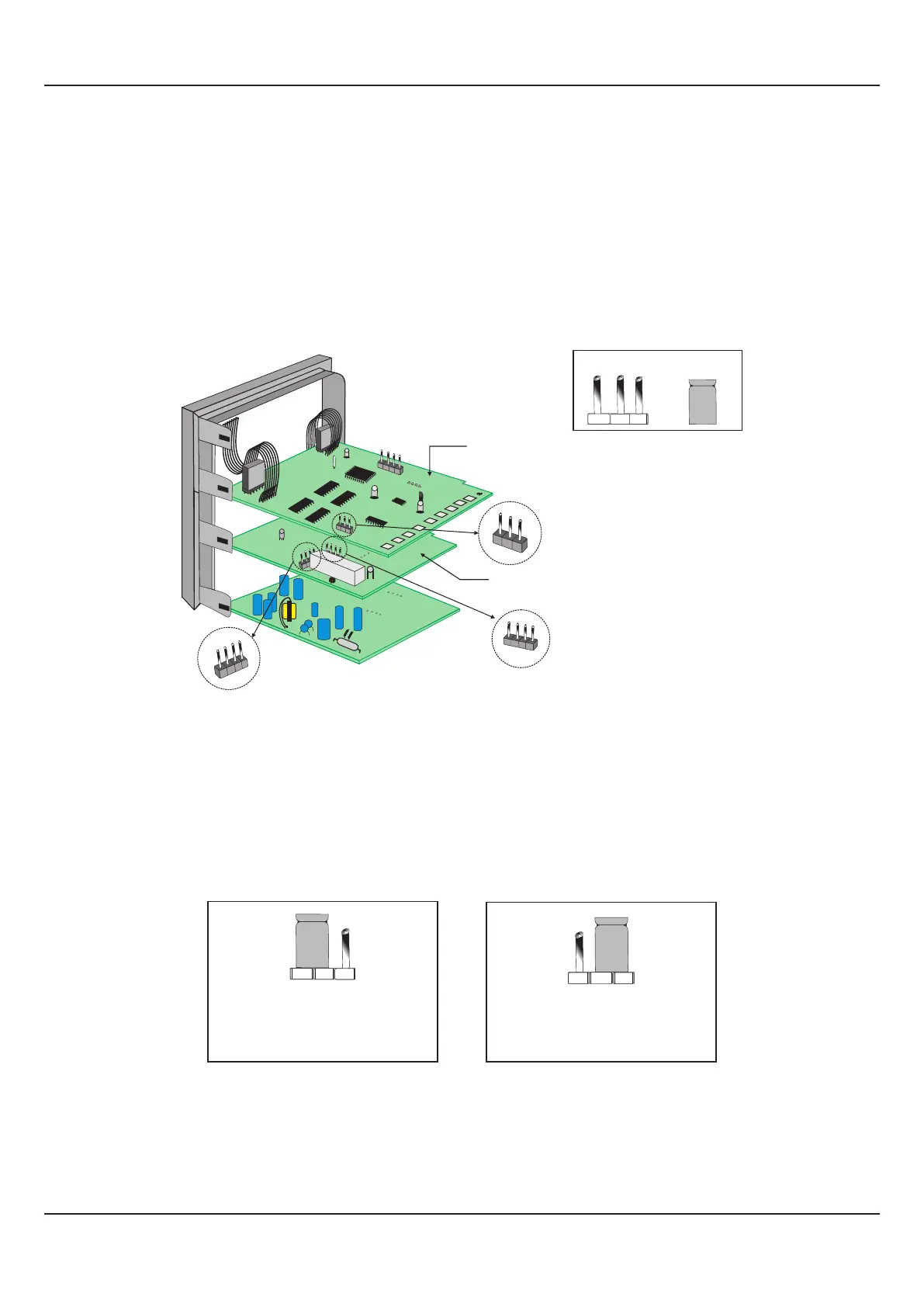
Figure 12.3
INPUT : Jumper Settings
In addition to parameter settings, the Input Type selection also requires proper jumper settings. For the jumper settings; Pins &
Shorting-Link arrangement, marked ‘A’, is provided on the CPU PCB as shown in Figure 12.3.
For DC Linear Current Inputs (0-20 mA or 4-20 mA), short the Pins 2 & 3 using Shorting-Link as shown in Figure 12.4 (b). For
all other Input types, short the Pins 1 & 2 using Shorting-Link as shown in Figure 12.4 (a).
Figure 12.4 (a)
For Input Types:
Thermocouples, RTD Pt100,
mV & V
1 2 3
Figure 12.4 (b)
For Input Types:
DC Linear Current (mA)
1 2 3
OUTPUT-1 : Jumper Settings
The Output-1 Type is user selectable as Relay, SSR, DC Volts or DC Current. Besides the parameter settings, the Output-1
configuration requires proper jumper settings. The jumper setting are provided as Pins & Shorting Link arrangement (marked
‘B’ & ‘C’) on Output PCB, as shown in Figure 12.3 and listed in Table 121.1 below.
User Manual
FLOREX
28
Shorting
Link
Pins
CPU PCB
1 2 3
A
1 2
3
4
C
1 2
3
4
Output PCB
Input
Jumper Settings
Output-1
Jumper Settings
Output-1
Jumper Settings
B