HARDWARE ASSEMBLY AND CONFIGURATIONS
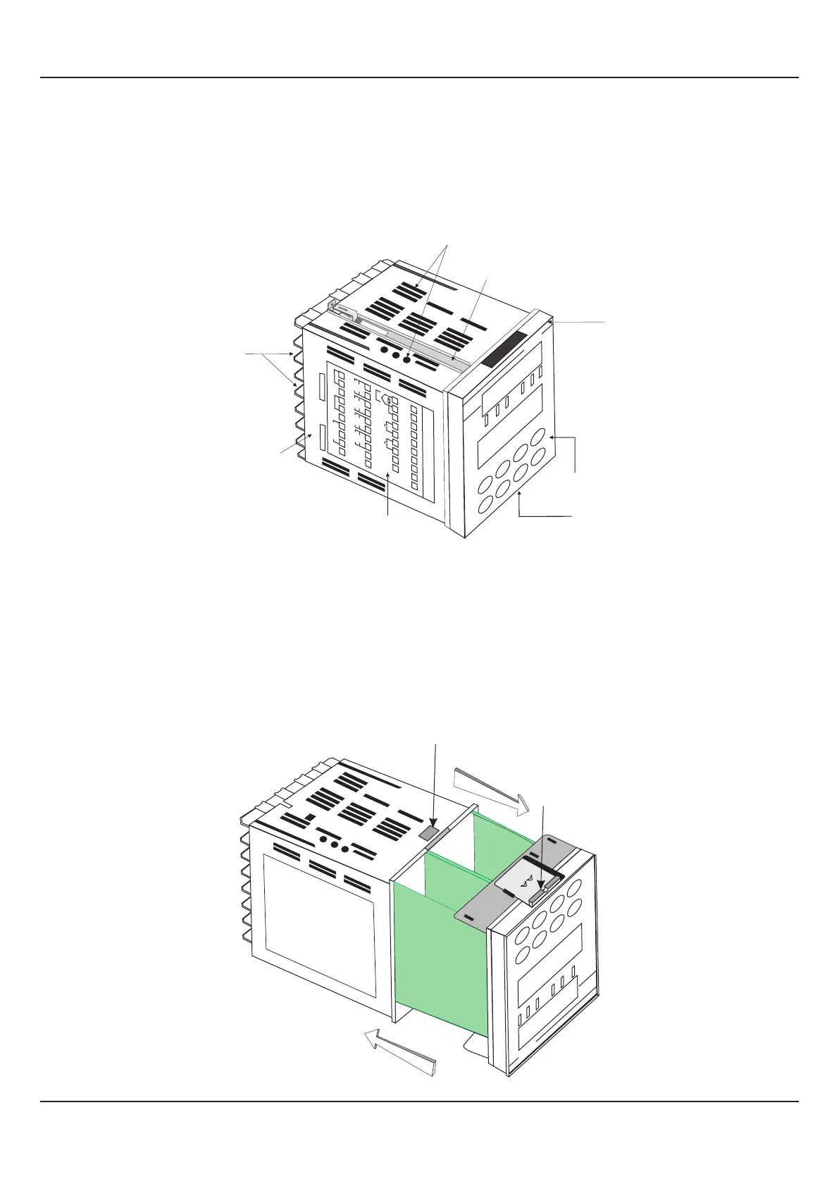
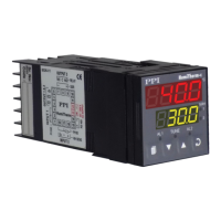
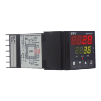
The Figure 12.1 below shows the indicator outer-case viewed with front label upright.
Figure 12.1
ELECTRONIC ASSEMBLY
The basic electronics assembly (without any plug-in modules), comprises of 4 Printed Circuit Boards (PCB). When viewed
from the front; the CPU PCB is to the left, Power-supply PCB is to the right, Output PCB is in the center and the Display PCB is
behind the bezel.
The electronic assembly can be removed from the plastic enclosure and placed back as described and illustrated in Figure
12.2.
Figure 12.2
User Manual
FLOREX
Removal
Placing Back
PulloutLatch
Latching Slot
PPI
FLOREX
Section 12
27
PPI
FLOREX
+
+
+
–
–
–
+
–
NO
C
NO
NO
NO
C
C
C
RL
Y
RLY
RL
Y
RL
Y
SSR / DC Lin
OP-1
SSR / DC Lin
OP-2
OP-3
OP-4
SSR
SSR
21
22
23
24
25
26
27
28
29
30
11
12
13
14
15
16
17
18
19
20
+
–
L
N
Ext. Voltage
B+
B
–
GND
SERIAL COMM
85 to 265 V
AC
1
2
3
4
5
6
7
8
9
10
+
+
–
–
DC LINEAR
DI-1
DI-2
T/C
Pt100
31
32
33
34
35
36
37
38
39
PPI
FLOREX
Sr.No.:
IO Code:
Ventilations
Bezel
Front Label
Connection Diagram
Rear
Terminals
Enclosure
Panel Mounting
Clamp
Pullout
Latch