ELECTRICAL CONNECTIONS
WARNING
MISHANDLING / NEGLIGENCE CAN
RESULT IN PERSONAL DEATH OR
SERIOUS INJURY.
1. The user must rigidly observe the Local Electrical Regulations.
2. Do not make any connections to the unused terminals for making a tie-point for other wires (or for any other reasons) as
they may have some internal connections. Failing to observe this may result in permanent damage to the FLOREX.
3. Run power supply cables separated from the low-level signal cables (like DC voltage/current, etc.). If the cables are run
through conduits, use separate conduits for power supply cable and low level signal cables.
4. Use appropriate fuses and switches, wherever necessary, for driving the high voltage loads to protect the FLOREX from
any possible damage due to high voltage surges of extended duration or short-circuits on loads.
5. Take care not to over-tighten the terminal screws while making connections.
6. Make sure that the FLOREX supply is switched-off while making / removing any connections or removing the FLOREX
from its enclosure.
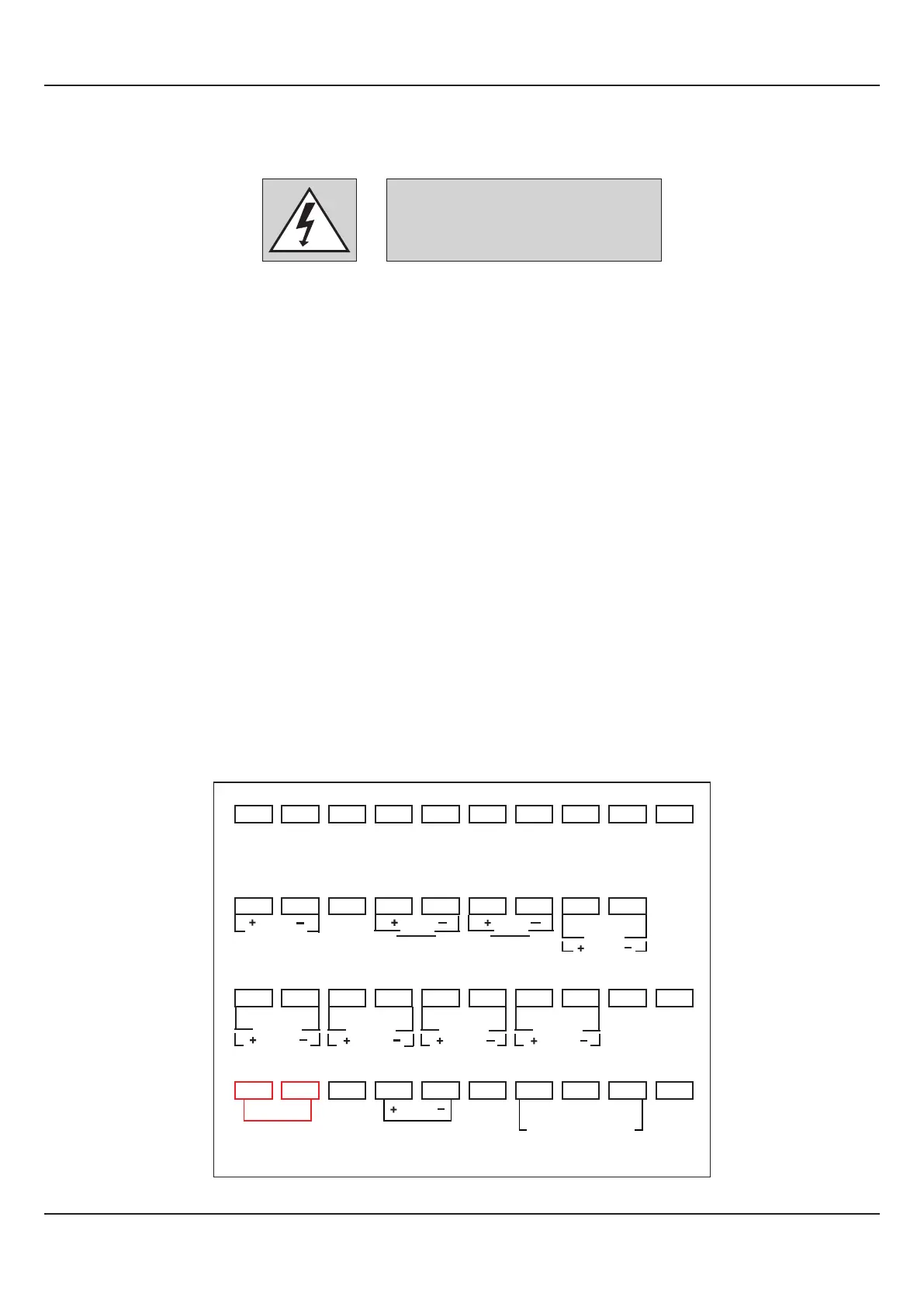
CONNECTION DIAGRAM
The Electrical Connection Diagram is shown on the left side of the FLOREX enclosure. The diagram shows the terminals
viewed from the REAR SIDE with the FLOREX label upright. Note that the Alarm Outputs and the Serial Comm. are applicable
only if the respective plug-in modules are fitted.
The rear panel electrical wiring connection diagram is shown in Figure14.1 below.
Figure 14.1
User Manual
FLOREX
35
Section 14
DC Linear
Analog
Input
Digital
Input-1
Digital
Input-2
NO
RLY
SSR / DC Lin
OP-5
C
NO
RLY
SSR
Total AL-2
C
NO
RLY
SSR
Total AL-1
C
NO
RLY
SSR
Flow AL-2
C
NO
RLY
SSR
Flow AL-1
C
B-
GND
SERIAL COMM
Ext. Voltage
L
N
85 ~ 265 V
AC SUPPLY
B+
1
2
3
4
5
6
7
8 9 10
11
12
13
14 15
16
17
18
19
20
31
32
33
34 35
36
37
38
39
21
22
23 24 25
26
27
28
29
30