DESCRIPTIONS
The back panel connections are described as under:
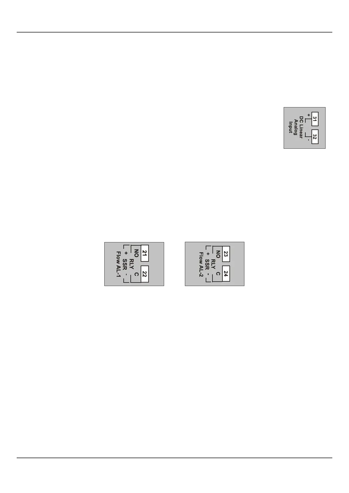
INPUT (Terminals 31 and 32)
The FLOREX accepts DC Linear Current/Voltage (mV,V,mA) as input from Flowmeters. The types and ranges are described
in Section 6 : Retransmission Parameters.
DC linear mV / V / mA
Use a shielded twisted pair with the shield grounded at the signal source for connecting DC Linear
Voltage (mV / V) source. Connect common (-) to terminal 32 and the signal (+) to terminal 31, as
shown in Figure 14.2. The DC Linear Current (mA) source is also connected in the similar way.
Figure 14.2
OUTPUT- 1 (Terminals 21 and 22) & OUTPUT- 2 (Terminals 23 and 24)
The Output-1 module and Output-2 (if fitted) can be configured as either Relay or DC Voltage pulses for driving SSR for Flow
Alarm-1 and Flow Alarm-2 output. The configuration is through hardware jumper settings. The Jumper setting for Output-1 is
available on the CPU board and for Output-2 is available on the module.
Similar to Output-1, the Output-2 module (if fitted) can be configured as either Relay or DC Voltage pulses for driving SSR for
Alarm.
The terminals for Relay, DC Voltage pulses output for SSR for Output-1 and Output-2 are shown in Figure 14.3(a), 14.3(b),
respectively.
Figure 14.3(b)
Relay / SSR Connections
for Flow Alarm-2
Figure 14.3(a)
Relay / SSR Connections
for Flow Alarm-1
Relay
Potential-free Relay changeover contacts N/O (Normally Open), C (Common) and N/C (Normally Close); rated 2A/240 VAC
(resistive load) are provided as Relay output.
Drive for SSR
DC Voltage level is generated for switching the external SSR (Solid State Relay). Connect (+) and (-) terminals of SSR to
terminals marked as (+) & (-), respectively. Use zero-crossover, 3 to 30 VDC operated SSR, rated approximately 1.5 times the
actual load rating. Use appropriate Heat Sink for mounting the SSR for load rating exceeding 10 A in case the Alarm Function is
used for tripping the loads.
OUTPUT- 3 (Terminals 25 and 26) & OUTPUT- 4 (Terminals 27 and 28)
Similar to the Output-1 module and Output-2 (if fitted), the Output-3 (if fitted) and Output-4 (if fitted) can be configured as either
Relay or DC Voltage pulses for driving SSR for Total Alarm-1 and Total Alarm-2 output. The configuration is through hardware
jumper settings available on the respective module.
The terminals for Relay, DC Voltage pulses output for SSR for Output-3 and Output-4 are shown in Figure 14.4(a), 14.4(b),
respectively.
User Manual
FLOREX
36