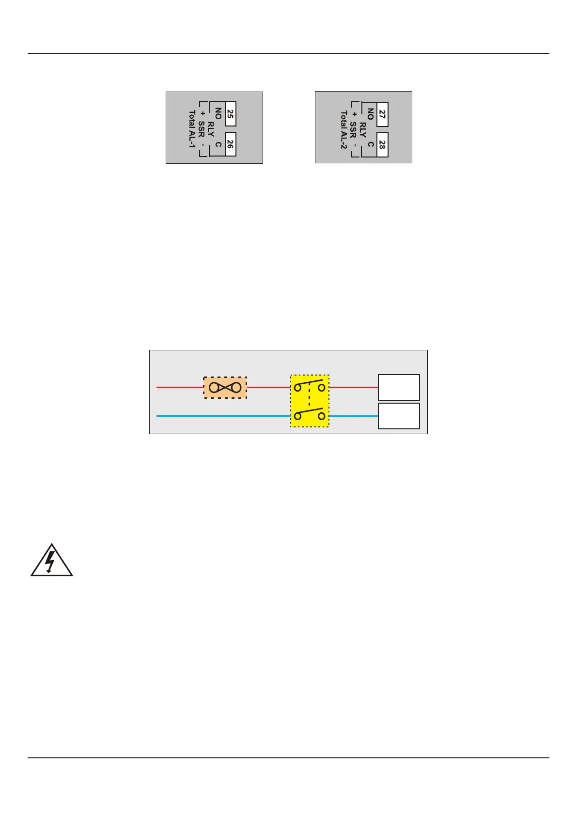
Figure 14.4(b)
Relay / SSR Connections
for Total Alarm-2
Figure 14.4(a)
Relay / SSR Connections
for Total Alarm-1
Relay
Potential-free Relay changeover contacts N/O (Normally Open), C (Common) and N/C (Normally Close); rated 2A/240 VAC
(resistive load) are provided as Relay output.
Drive for SSR
DC Voltage level is generated for switching the external SSR (Solid State Relay). Connect (+) and (-) terminals of SSR to
terminals marked as (+) and (-), respectively.
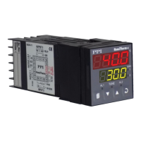
POWER SUPPLY (Terminals 1 & 2)
Figure 14.5
As standard, the FLOREX is supplied with power connections suited for 85 to 264 VAC line supply. Use well-insulated copper
conductor wire of the size not smaller than 0.5mm² for power supply connections. Connect Line (Phase) supply line to terminal
1 and the Neutral (Return) supply line to terminal 2 as shown in Figure 14.5 above. The FLOREX is not provided with fuse and
power switch. If necessary, mount them separately. Use a time lag fuse rated 1A @ 240 VAC.
For DC Supply, connect Signal (+) & Common (-) to FLOREX terminals 1 & 2, respectively.
The FLOREX is designed for installation in an enclosure which provides adequate protection against electric
shock. Local regulations regarding electrical installation should be rigidly obsereved. Consideration should be
given to prevention of access to the Power Supply terminals by unauthorised personel. If the Relay contacts are
to carry mains (line) voltage, it is recommended that the Relay contacts mains (line) supply should be switched
and fused in a similar manner but should be separate from the FLOREX mains (line) supply.
Warning
SERIAL COMMUNICATION PORT (Terminals 7 and 8)
If the optional plug-in communication board is fitted, connect terminal 7 and 8 of the FLOREX to (+) and (-) terminals of the
Master device. In case of RS485 port, connect terminal 7 and 8 of the FLOREX to (+) and negative (-) terminals of the master
device. In case of RS232 port connect terminal 7 to TXD (Transmit) and Terminal 8 to RXD (Receive) and Terminal 9 to GND
(Ground).
To ensure reliable operation of the Serial Communication Link (without data corruption due to line noise or reflections), use a
pair of twisted wires inside screened cable with the terminating resistor (100 to 150 Ω) at one end, as shown in Figure 14.6.
User Manual
FLOREX
37
Line
Neutral
1 (L)
2 (N)
2 Pole
Isolating Switch
Fuse
Power Supply
Terminal