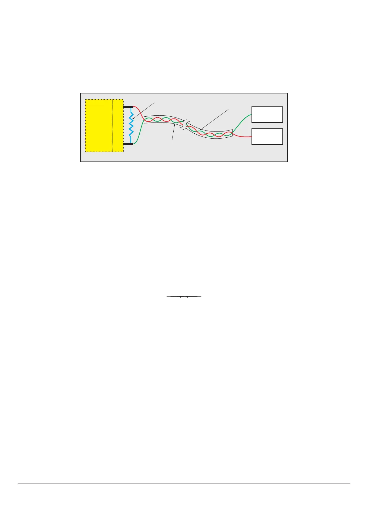
SERIAL COMMUNICATION PORT (Terminals 7 & 8)
Figure 14.6
Notes :
1. The communication cable should be a pair of twisted wires inside screened cable as shown in Figure 14.6 above. It should have less
than 100 ohms / km nominal DC resistance (Typically 24 AWG or thicker). Connect the terminating resistor (Typically 100 to 150 ohm) at
one end to improve noise immunity.
2. Run the communication cables separated from cables (like power supply, Relay/Contactor cables etc.). If the cables are run through
conduit use a separate conduit for communication cables.
3. Communication cables may run through low level signal cables (like DC Linear Current/Voltage outputs) if these cables are not exposed
to an interference source.
4. Do not use redundant wires in communication cables for other signals.
5. Ensure that the cable is ‘daisy chained’ between FLOREXs for multi-dropped wiring. That is, run from one FLOREX to the next to the
final FLOREX in the chain.
User Manual
FLOREX
38
Terminating Resistor
Screened Cable
Twisted
Wire Pair
(100 to 150 Ohms)
8 (B-)
7 (B+)
HOST
B-
B+
Master Device
Serial Comm.
Terminals