The following precautions should be strictly observed while installing the indicator:
1. The place of installation should be free of corrosive/combustible gases and electrically conductive pollution.
2. Ensure that the place of installation is not subject to rapid ambient changes that can cause condensation. Also the Ambient
Temperature and Relative Humidity surrounding the indicator should not exceed the maximum specified for the proper
operation of the indicator.
3. The place of installation should be adequately protected against excessive electrostatic or electromagnetic interference.
4. The indicator should not be subject to direct vibration or shock.
5. The indicator should not be exposed to dust, salt air, direct sunlight or radiant heat.
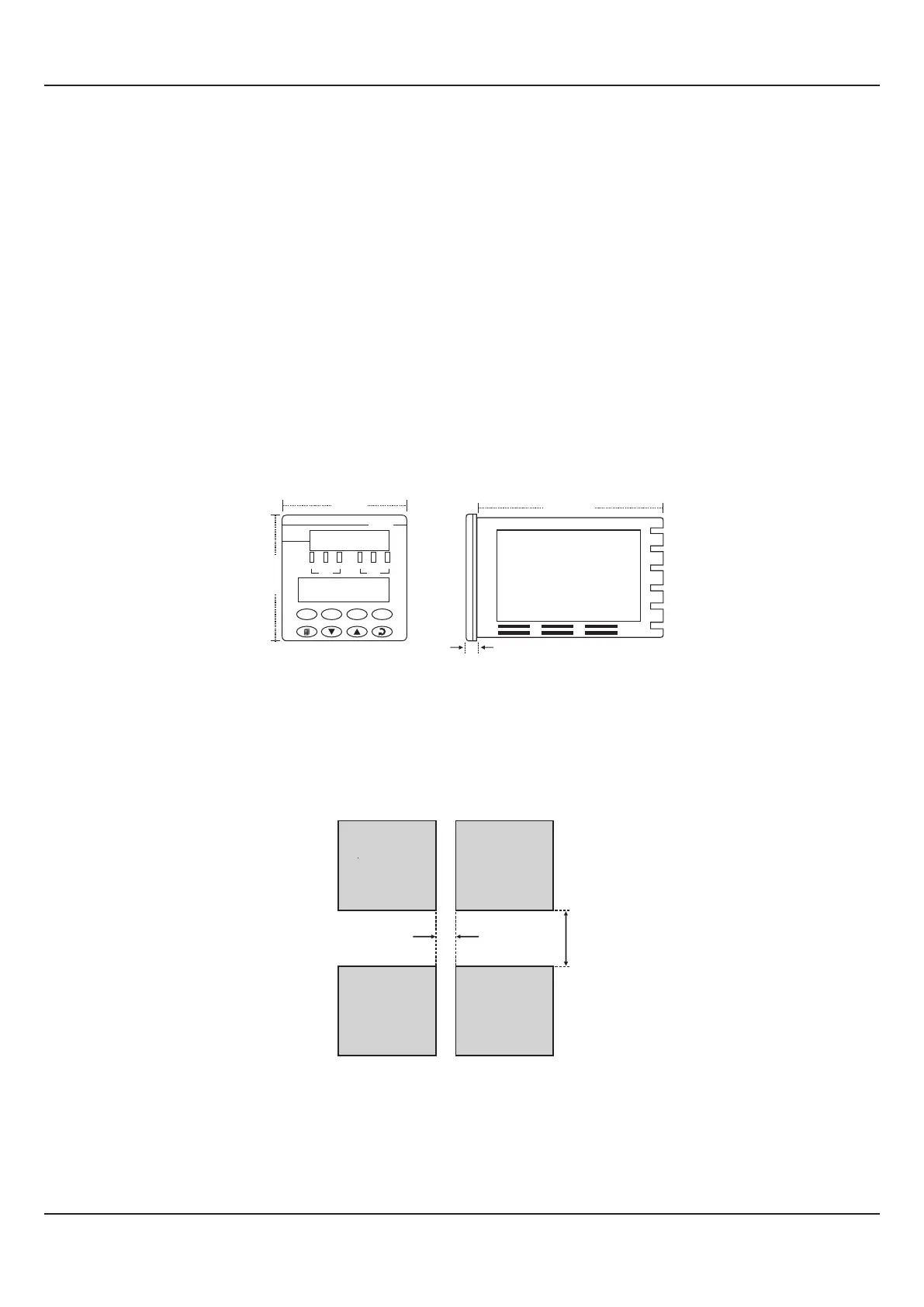
OUTER DIMENSIONS
The Figure 13.1 shows the outer dimensions of the indicator.
MECHANICAL INSTALLATION
Figure 13.1
Side View
100 mm
(4 in)
0.8 mm
Front View
PPI
FLOREX
96 mm
(3.78 in)
96 mm
(3.78 in)
RST SCR
ACK OPR
AL1 AL2 SQR
RATE
AL1 AL2 OVR
TOTAL
PANEL CUTOUT AND RECOMMENDED MINIMUM SPACING
The Figure 13.2 shows the panel cutout requirements for a single indicator and also the minimum spacing recommended if
several indicators are required to be mounted on a single panel.
Panel Cutout
92 X 92 mm
-0, +0.5 mm
(3.62 X 3.62 in)
(-0, +0.02 in)
10mm (0.39in)
38mm (1.5in)
Figure 13.2
PANEL MOUNTING
Follow the steps below for mounting the indicator on panel:
1. Prepare a square cutout to the size shown in Figure 13.2.
2. Remove the Panel Mounting Clamp from the indicator Enclosure.
User Manual
FLOREX
33
Section 13