Metallic Projection
+
+
+
–
–
–
+
–
NO
C
NO
NO
NO
C
C
C
RLY
RL
Y
RL
Y
RLY
SSR / DC Lin
OP-1
SSR / DC Lin
OP-2
OP-3
OP-4
SSR
SSR
21
22
23
24
25
26
27
28
29
30
1
1
12
13
14
15
16
17
18
19
20
+
–
L
N
Ext. Voltage
B+
B
–
GND
SERIAL
COMM
85 to 265 VAC
1
2
3
4
5
6
7
8
9
10
+
–
+
+
–
–
NO
C
RLY
DC LINEAR
DI-1
DI-2
SSR / DC Lin
OP-5
T/C
Pt100
31
32
33
34
35
36
37
38
39
PPI
neuro 102 EX
Sr
.No.:
IO Code:
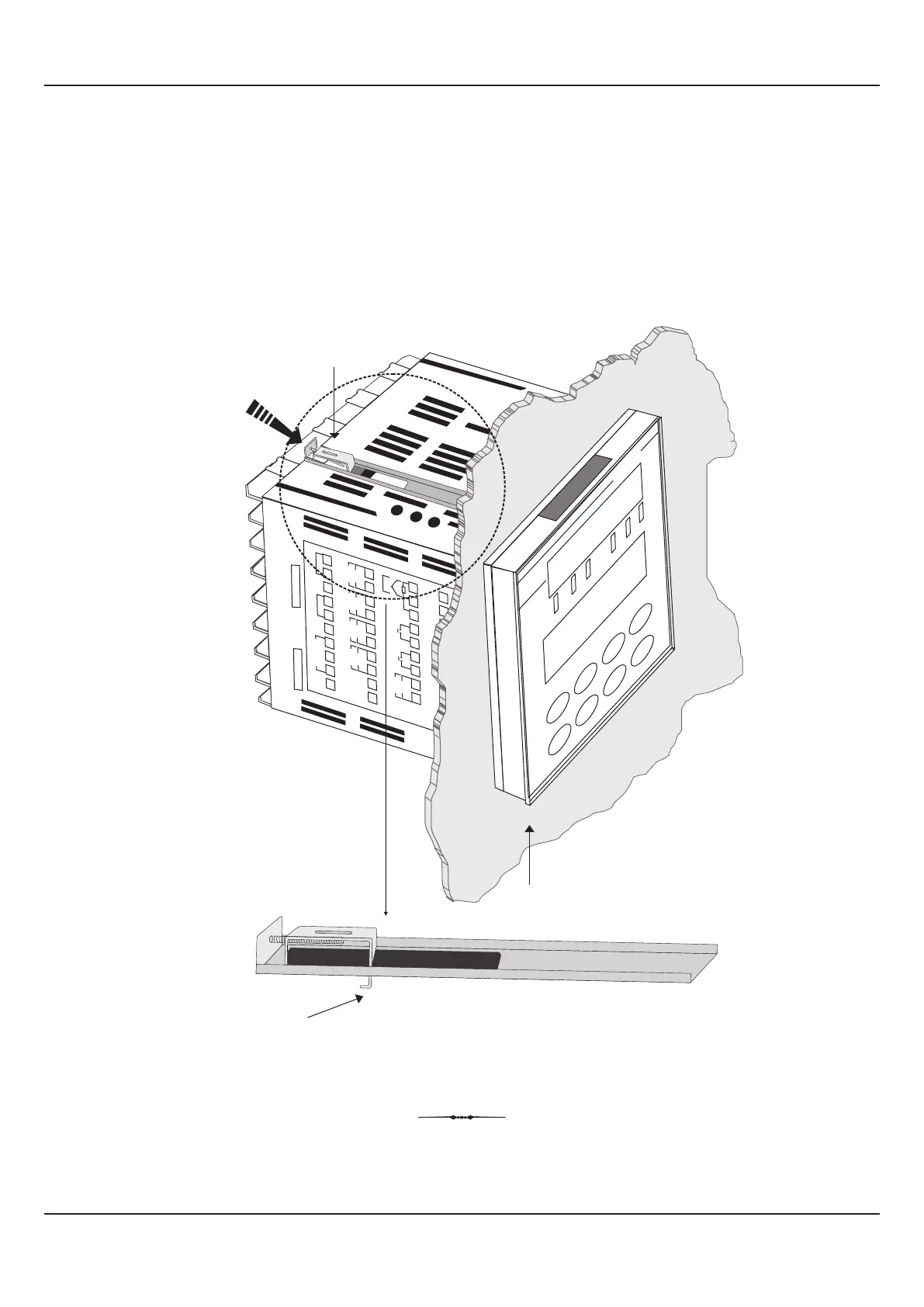
Tighten the
screw
Panel Mounting
Clamp
Mounting Panel with
Square Cutout
PPI
FLOREX
3. Insert the rear of the indicator housing through the panel cutout from the front of the mounting panel.
4. Hold the indicator gently against the mounting panel such that it positions squarely against the panel wall (see Figure
13.3). Apply pressure only on the bezel and not on the front label.
5. Fix the Mounting Clamps (one after the other) such that the metallic projection fits in the square hole provided on the top
and bottom sides of the enclosure. Tighten the clamp screw until the clamps firmly secures against the panel wall.
Figure 13.3
User Manual
FLOREX
34