Do you have a question about the PPI neuro 102L Plus and is the answer not in the manual?
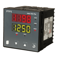
Explains the primary display mode showing PV and Setpoint values.
Step-by-step guide to adjusting the Setpoint value in Main Display Mode.
Guide to activating and de-activating Manual Mode for open-loop control.
Steps for entering and operating the Set-up Mode to view/modify parameters.
Procedure for enabling/disabling the Master Lock feature to protect parameters.
Steps to unlock the controller by repeating the locking procedure.
Sets proportional gain (% power per unit error) for PID control.
Sets integral time constant in seconds for PID control.
Sets derivative time constant in seconds for PID control.
Sets 'On + Off' time for time modulating power output in PID.
Sets differential band for On-Off switching for OP1.
Selects Alarm-1 activation type: None, Process Low, Process High, Deviation, Window.
Sets the Alarm limit for Process High or Process Low Alarm-1.
Sets deviation limit from setpoint for Deviation Band Alarm-1.
Sets symmetrical deviation limits for Window Band Alarm-1.
Sets differential band for Alarm-1 switching ON/OFF states.
Selects Alarm-2 activation type: None, Process Low, Process High, Deviation, Window.
Sets the Alarm limit for Process High or Process Low Alarm-2.
Selects appropriate Control Algorithm: On-Off, Pulse, PID.
Selects Reverse (heat logic) or Direct (cool logic).
Sets the minimum permissible control setpoint value.
Sets the maximum permissible control setpoint value.
Selects input type for process value measurement (Thermocouple, RTD, mV/V/mA).
Sets transmitter output signal value for PV RANGE LOW.
Sets transmitter output signal value for PV RANGE HIGH.
Sets process value indication resolution (decimal point).
Sets process value corresponding to SIGNAL LOW parameter.
Sets process value corresponding to SIGNAL HIGH parameter.
Initiates a new tuning cycle or aborts an ongoing tuning operation.
Enables or Disables the setpoint profile feature.
Sets the number of segments to constitute the setpoint profile.
Sets the number of times the profile is to be repeated (cycled).
Defines action (Abort/Continue) on power failure during profile execution.
Selects profile segment number for editing parameters.
Sets the Target (End) value for the selected profile segment.
Highlights severe risks from mishandling or negligence during installation.
| Brand | PPI |
|---|---|
| Model | neuro 102L Plus |
| Category | Controller |
| Language | English |