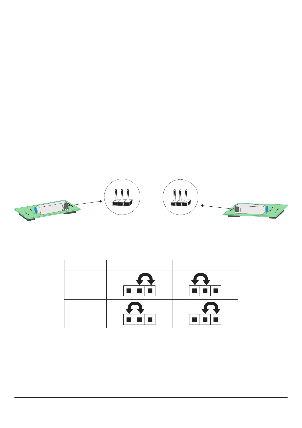
Each Module is provided with one 4-Pin & one 5-Pin Female Socket that can directly fit into corresponding male plugs provided
on either Output PCB (OP2, OP3 & OP4) or CPU PCB (OP5). Refer Figure12.5(a) & 12.5(b). These modules are either pre-
fitted while the indicator is shipped from the factory or can be fitted later by the user.
The Figure12.5(a) shows the 4 & 5 Pin Female Socket mounted on the bottom side of the output modules. The Figure 12.5(b)
shows the 4 & 5 Pin Male Plugs Mounted on the CPU & Output PCBs. For clarity, the modules and the Power-Supply PCB are
not shown in the figure.
The Figure12.6 shows the Output Modules fitted in their respective positions on the CPU & Output PCBs. For OP2, OP3 &
OP4 modules; push the modules towards front for mounting and pull the modules towards back for removal. For OP5 module;
push the module towards right for mounting and pull the module towards left for removal.
(a) Relay / SSR Module
The Relay/SSR Module is supported by OP2, OP3 & OP4.The module can be configured to function as either Relay or SSR
Output by appropriate jumper settings, ‘A’ and ‘B’,as shown in Figure 12.7(a) & 12.7(b) and Table 12.2 below. Use Shorting -
Link for jumper settings.
Jumper Settiig-A
1 2 3
Jumper Setting ‘A’ - Viewed facing module
Figure 12.7(a)
Jumper Settiig-B
1 2 3
Jumper Setting ‘B’ - Viewed facing module
Figure 12.7(b)
User Manual
FLOREX
31
Table 12.2
Relay
SSR
Output Type Jumper Setting - A Jumper Setting - B
(b) DC Linear Voltage Module
(c) DC Linear Current Module
The DC Linear Module, shown in Figure 12.8 below, is factory configured for either Current or Voltage output and is supported
by OP2 & OP5. The DC Current Module can be configured to output either 0-20 mA or 4-20 mA by appropriate parameter
setting. Similarly, the DC Voltage Module can be configured to output either 0-5 V or 0-10 V by appropriate parameter settings.