CONVERTISSEUR A ISOLATION
GALVANIQUE
Type 2204
Sommaire
Avertissements . . . . . . . . . . . . . . . . . . . . . . . . . . . . . . . . . 26
Consignes de sécurité. . . . . . . . . . . . . . . . . . . . . . . . . . . . 28
Déclaration de conformité CE. . . . . . . . . . . . . . . . . . . . . . 30
Démontage du SYSTEME 2200 . . . . . . . . . . . . . . . . . . . . 31
Applications. . . . . . . . . . . . . . . . . . . . . . . . . . . . . . . . . . . . 32
Caractéristiques techniques . . . . . . . . . . . . . . . . . . . . . . . 32
Entrée . . . . . . . . . . . . . . . . . . . . . . . . . . . . . . . . . . . . . . . . 32
Sortie . . . . . . . . . . . . . . . . . . . . . . . . . . . . . . . . . . . . . . . . . 33
Spécifications électriques . . . . . . . . . . . . . . . . . . . . . . . . . 33
Référence de commande . . . . . . . . . . . . . . . . . . . . . . . . . 35
Schéma de principe . . . . . . . . . . . . . . . . . . . . . . . . . . . . . 35
Configuration. . . . . . . . . . . . . . . . . . . . . . . . . . . . . . . . . . . 36
2524
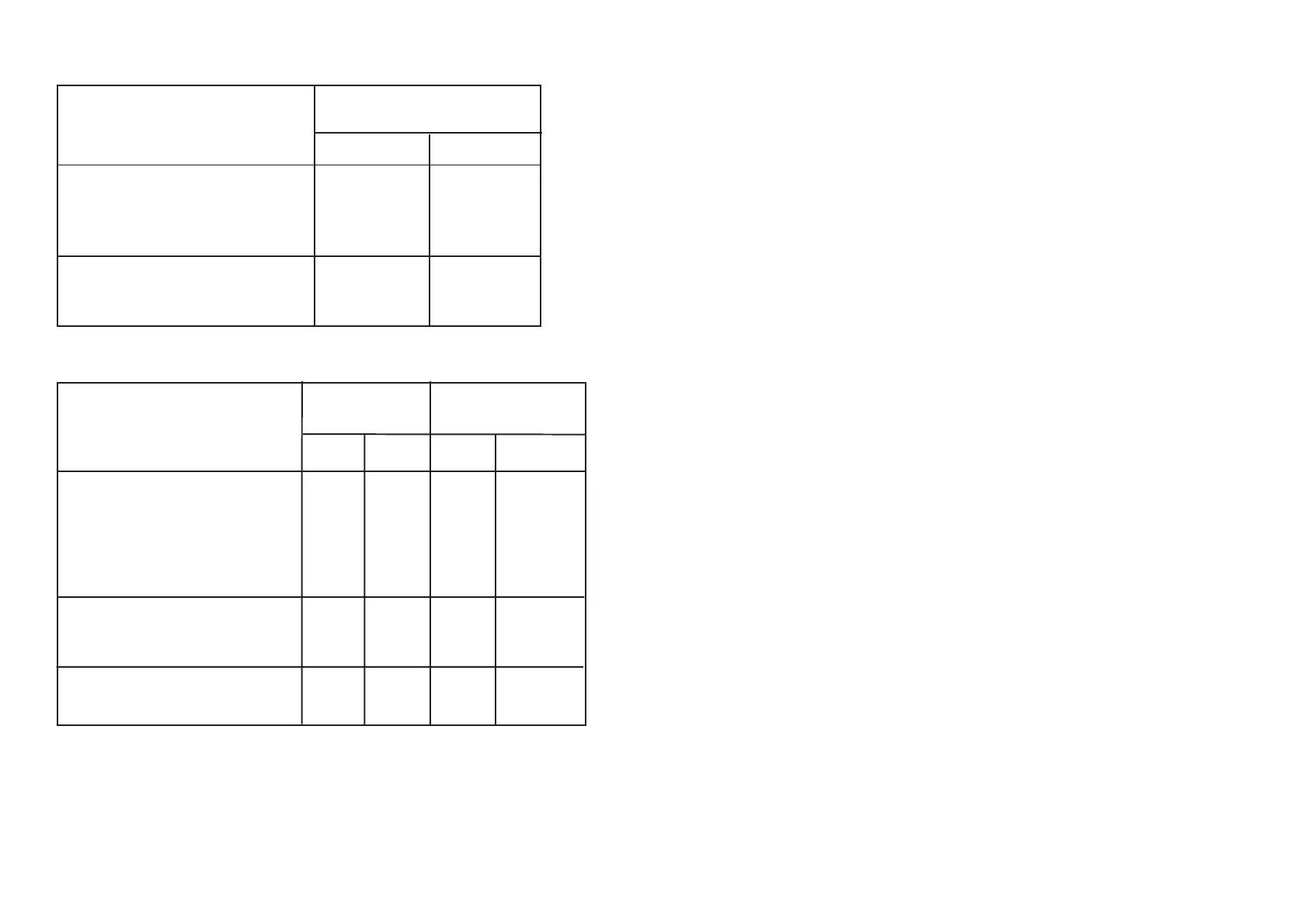
PROGRAMMING:
INPUT DP1 (10-pole)
PROGRAMMING SW 1, 2, 3, 4, 5
SW ON SW OFF
0...5 mA 1, 3 2, 4, 5
0...20 mA 1, 4 2, 3, 5
0...1 V 2, 3 1, 4, 5
0...2.5 V 2, 4 1, 3, 5
0...10 V 2, 3, 4 1, 5
For 20% offset on input,
set DP1 SW5 ON
e.g. input 4...20 mA 1, 4, 5 2, 3
OUTPUT DP2 (4-pole) DP1 (10-pole)
PROGRAMMING SW 1 - 4 SW 6, 7, 8, 9, 10
SW ON SW OFF ON OFF
0...5 mA 4 1, 2, 3 7 6, 8, 9, 10
0...20 mA 3 1, 2, 4 8 6, 7, 9, 10
0...5 mA / 0...250 mV 1, 4 2, 3 6 7, 8, 9, 10
0...20 mA / 0...1 V 1, 3 2, 4 6, 7 8, 9, 10
0...5 mA / 0...2.5 V 2, 4 1, 3 6, 8 7, 9, 10
0...20 mA / 0...10 V 2, 3 1, 4 6, 7, 8 9, 10
For 20% offset on output,
set DP1 SW9 ON
e.g. output 4...20 mA 3 1, 2, 4 8, 9 6, 7, 10
For reversed output set DP1,
SW10 ON e.g. output 20...4 mA 3 1, 2, 4 8, 9, 10 6, 7
Note: At other spans than the above-mentioned, DP1 and DP2 have a different
setting which applies to the delivered special range.
 Loading...