32
33
ISOLATEUR D’IMPULSIONS
PRecon 5202B
Sommaire
Avertissements ................................................................... 34
Consignes de sécurité ....................................................... 35
Déclaration de conformité CE ............................................ 37
Démontage du SYSTEME 5000 ......................................... 38
Application ......................................................................... 39
Caractéristiques techniques............................................... 39
Montage / installation ......................................................... 39
Applications ........................................................................ 40
Référence de commande ................................................... 41
Spécifications électriques .................................................. 41
Programmation des cavaliers ............................................. 44
Déscription des fonctions .................................................. 45
Schéma de principe 5202B1 et 5202B2 ............................ 46
Schéma de principe 5202B4 .............................................. 47
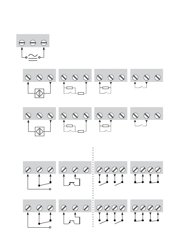
Connexions ........................................................................ 48
Appendice :
UL Control Drawing No. 5202QU01................................... 65
31 32 33
43
41 42
Rp
Rs
53
51 52
Rp
Rs
43
41 42
+
-
53
51 52
+
-
43
41 42
53
51 52
53
51 52
Rp
43
41 42
Rp
11 12
13
11 12
13
+
-
Rp = 15 k
Rs = 750
Ω
Ω
Rp = 15 k
Rs = 750
Ω
Ω
11 12
14
13
11 12
14
13
21 22 24
23
21 22 24
23
23
21 22
+
-
23
21 22
Supply:
Outputs:
Channel 1Channel 2
Channel 2
Inputs:
Contact
Relay
Open
collector, NPN
Open
collector, NPN
NAMUR sensor Contact, cable error Contact, cable error
Contact
Relay
NAMUR sensor Contact, cable error Contact, cable error
to be mounted
on contact
to be mounted
on contact
5202B4:
2 x Relay N.O. 2 x Relay N.C.
2 x Relay N.C.2 x Relay N.O.
5202B1 and 5202B2: