Power up
0000
PASSW.
Txt 1
50.0
%
12.0
3
3
0000
9999
1 2
NO
ADV.SET
Txt 2
NO
YES
1 2
3
VOLT
IN TYPE
Txt 3
VOLT
CURR
LIN.R
POTM
TEMP
1 2
3
2-10
V.RANGE
Txt 4
2-10
0-10
1-5
0-5
0.2-1
0-1
1 2
3
YES
ADV.SET
Txt 2
3
0.0
DISP.LO
Txt 13
999.9
-199.9
1 2
111.1
DEC.P
Txt 12
1111
111.1
11.11
1.111
1 2
3
UNIT
%
Txt 11
@C
mA
rpm
(69 units)
1 2
3
1.1
1.0
CURR
IN TYPE
Txt 3
3
4-20
I.RANGE
Txt 5
3
LIN.R
IN TYPE
Txt 3
3
3W
CONNEC.
Txt 6
2W 3W 4W
1 2
3
POTM
IN TYPE
Txt 3
3
TEMP
IN TYPE
Txt 3
0
R 0%
Txt 7
3
2500
R 100%
Txt 8
1 2
3
Cu
SENSOR
Txt 10
Cu Pt Ni TC
1 2
3
10
Cu TYPE
Txt 69
10...100
3
3W
CONNEC.
Txt 6
2W 3W 4W
1 2 1 2
0...9999
1 2
0...9999
3
0-20 4-20
1 2
TC.B TC.E TC.J TC.K TC.L
TC.N TC.R TC.S TC.T TC.U
TC.W3 TC.W5 TC.Lr
1 2
Pt
SENSOR
Txt 10
3
Ni
SENSOR
Txt 10
3
TC
SENSOR
Txt 10
3
100
Pt TYPE
Txt 16
3
3W
CONNEC.
Txt 6
100
Ni TYPE
Txt 17
3
3W
CONNEC.
Txt 6
TC.K
TC.TYPE
Txt 18
3
INT
CJC
Txt 63
10...1000
2W 3W 4W
1 2 1 2
50...1000
2W 3W 4W
1 2 1 2
20 4114V104-UK
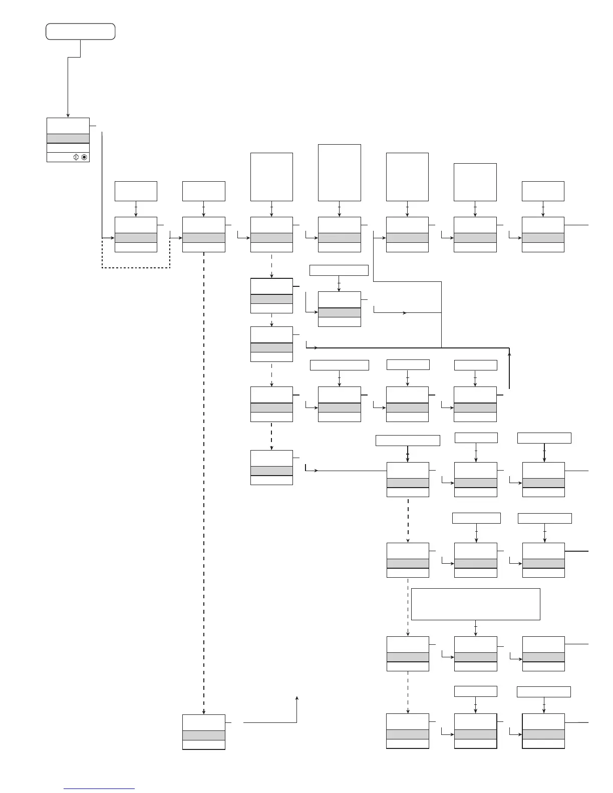
1.0=Defaultstate
Line 1 shows input
signal.
Line 2 shows
UNIT.
By pressing 1 and
2 simultaneously
line 3 alternates
between A.Out
and TAG.
Line 4 shows com-
munication status.
1.1=Onlyifpassword-
protected.
1.2=Notvalidforthese
input signals:
0...20 mA and
voltage.
1.3=Onlyifinputsignal
is temperaure.
ROUTING DIAGRAM
If no key is activated for 1 minute, the display will return to the default
state 1.0 without saving configuration changes.
1 Increase value / choose next parameter
2 Decrease value / choose previous parameter
3 Accept the chosen value and proceed to the next menu
Hold 3 Back to previous menu / return to menu 1.0 without saving
Continued on the page
Routing diagram ADV.SET