6 5104V104-UK
HOW TO DEMOUNT SYSTEM 5000
First, remember to demount the connectors with hazardous voltages.
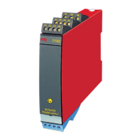
Picture 1:
By lifting the bottom lock, the device
is detached from the DIN rail.
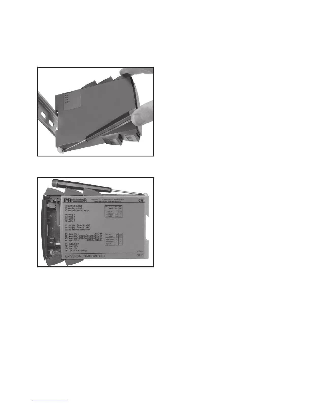
Picture 2:
Then, by lifting the upper lock and
pulling the front plate simultaneously
the PCB is removed.
Switches and jumpers can now be
adjusted.