Do you have a question about the PRECISION DIGITAL NOVA PD570 Series and is the answer not in the manual?
Details technical specifications including display, sampling time, power, and warranty.
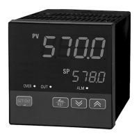
Explains the function of each key on the controller's front panel for operation and setting.
Describes the meaning and function of each LED indicator on the controller's front panel.
Configures input sensor types, display units, and temperature ranges for the controller.
Sets parameters for control operation, including set points, hysteresis, and output modes.
Configures alarm types, trigger points, deviation ranges, dead bands, and delay times.
Sets up retransmission modes and scales for analog output signals.
Configures communication protocols, baud rates, parity, data length, and addresses.
Provides physical dimensions and panel cutout requirements for unit installation.
Describes the procedure for physically mounting the controller into a panel.
Specifies the type and rating of the power cable to be used for connections.
Details the type of screw terminals and crimp connectors suitable for wiring.
Illustrates terminal layouts, connections, and electrical ratings for various functions.
Explains proper grounding procedures and power cable connection guidelines.
Details how to connect RTD, DC Voltage, and DC Current input signals.
Describes how to connect the retransmission output signal for external devices.
Explains how to connect the controller's relay outputs for alarm or control functions.
Provides guidance on using external relays, especially for switching inductive loads.
Details the wiring requirements for RS-485 serial communication.
| Model | PD570 Series |
|---|---|
| Housing Material | Polycarbonate |
| Mounting | Panel Mount |
| Input Types | Thermocouple, RTD |
| Output Type | Relay |
| Communication Protocols | Modbus RTU |
| Dimensions | 48 x 96 mm (1.89 x 3.78 in) |
| Enclosure | NEMA 4X, IP65 front |
| Approvals | CE, UL, cUL |
| Digits | 5 |