EasyManua.ls Logo

PRECISION DIGITAL PD765-6R5-10 User Manual

Default Icon
72 pages
To Next Page IconTo Next Page
Page #1 background imageLoading...
Page #1 background image
PRECISION DIGITAL CORPORATION
89 October Hill Road • Holliston MA 01746 USA
Tel (800) 343-1001 • Fax (508) 655-8990
www.predig.com
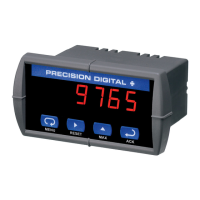
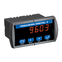
TRIDENT & TRIDENT X2
MODEL PD765
Instruction Manual
Accepts Current, Voltage, TC, & RTD Inputs
4 Digit Display, 0.56" (14 mm) or 1.20" (31 mm)
Linear or Square Root with Low-Flow Cutoff
Maximum/Minimum Display
Type 4X, NEMA 4X, IP65 Front
Universal Power Supply 85-265 VAC
12-36 VDC/12-24 VAC Power Option
Two Relays and 4-20 mA Output Option
24 VDC Transmitter Power Supply Options
USB, RS-232, & RS-485
Serial Communication Adapters Options
Free Modbus
®
RTU Protocol
Copy Meter Settings to Other Meters
Free MeterView
®
Software - Configuration & Data Acquisition

Table of Contents

Questions and Answers:

PRECISION DIGITAL PD765-6R5-10 Specifications

General IconGeneral
Digits5
MountingPanel mount
Display TypeLED
Input TypeThermocouple, RTD, Resistance, DC Voltage, DC Current
Input Range (Thermocouple)J, K, T, E, R, S, B, N, C, L
Voltage Range0-10 V
Current Range4-20 mA
Power Supply85-265 VAC
OutputsRelay
EnclosureNEMA 4X, IP65

Summary

SPECIFICATIONS

Process Input Specifications

Covers input types, accuracy, function, low-flow cutoff, temperature drift, and input overload.

Temperature Input Specifications

Details thermocouple and RTD types, resolution, accuracy, and sensor break detection.

Relays Option Specifications

Describes relay rating, noise suppression, deadband, alarm modes, and time delay.

Isolated 4-20 mA Output Specifications

Covers output range, scaling, accuracy, and transmitter power supply details.

Serial Communications Specifications

Details meter address, baud rate, transmit delay, data format, and parity settings.

SAFETY INFORMATION

INSTALLATION

Panel Mounting Procedure

Steps for preparing a panel cutout, mounting dimensions, and installing the meter with brackets.

Connections

Power Connections

Details on how to make power connections, including polarity and fuse requirements.

Signal Connections

Explains connections for current, voltage, and thermocouple/RTD inputs.

Switching Inductive Loads

4-20 mA Output & Input Signal Connections

SETUP AND PROGRAMMING

Front Panel Buttons and Status LED Indicators

Main Menu Navigation

Setting Up the Meter (SEtu)

Setting the Input Signal (inPE)

Setting the Relay Operation (ELY)

Setting the Relay Action

Setting Fail-Safe Operation

Relay and Alarm Operation

High Alarm with Fail-Safe Operation

Low Alarm with Fail-Safe Operation

Scaling the 4-20 mA Analog Output

Program the Sensor Break Output Value

Programming the Meter

Scaling the Meter

Calibrating the Meter

Recalibrating Temperature Inputs

Recalibration Procedure for Temperature Inputs

Recalibrating Process Inputs (ICAL)

Setting Up the Password

Advanced Features Menu

Advanced Features Menu & Display Messages

Offset Adjustment (Adj)

Noise Filter (FLtr)

Noise Filter Bypass (bYPS)

Serial Communications (SEL)

Select Menu (SELc)

Linear or Square Root Function (Linr or 59rt)

Low-Flow Cutoff (cutF)

MeterView® Software

Meter Copy Function (COPY)

Meter Cloning Instructions

Internal Calibration (ICAL)

TROUBLESHOOTING

Reset Meter to Factory Defaults

Factory Defaults & User Settings

Troubleshooting Tips

Related product manuals