25
PM-1030V v5 2020-10 Copyright © 2020 Quality Machine Tools, LLC
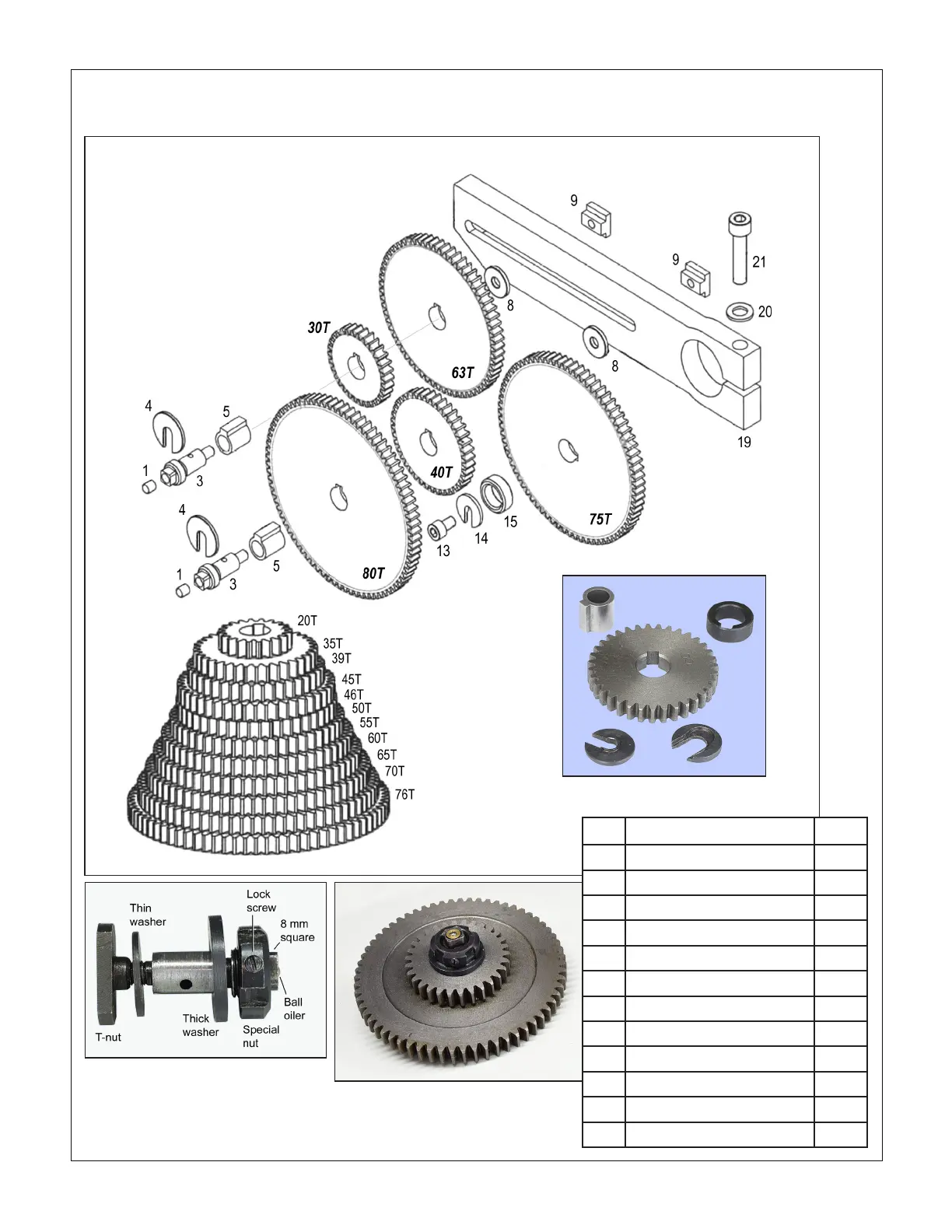
EXTERNAL CHANGE GEARS Fig 2
5
15
14
4
Adjustable gear axle
(Shipments from late 2017 on) Screw the axle into the T-nut, then tighten with an 8 mm
wrench. Install the gear(s) on the axle. Loosen the lock screw, then rotate the special
castellated nut to take up end-oat. Re-tighten the lock screw. This is typically a one-time
adjustment; thereafter the axle can be treated as a one-piece shoulder bolt.
Dimensions in millimeters
Ref Description Part
1 Oiler Φ6 Z1074
3 Gear axle Z1075
4 Special C-washer Z1076
5 Ext. keyed bushing Z1077
8 Thin spacer washer, special Z1078
9 T-nut Z1079
13 Skt hd cap screw M6 x 10 Z1080
14 Special C-washer Z1081
15 Int. keyed bushing Z1082
19 Change gear support bar Z1083
20 Washer Φ8 Z1084
21 Skt hd cap screw M8 x 35 Z1085
There may be detail dierences
between this representative drawing
and the machine as supplied
 Loading...


