TECH-TIP
TT.CON.20191023
Contact Precor Customer Support at support@precor.com or 800.786.8404 with any questions. Page 2 of 2
©2019 Precor Incorporated, Unauthorized reproduction and distribution prohibited by law.
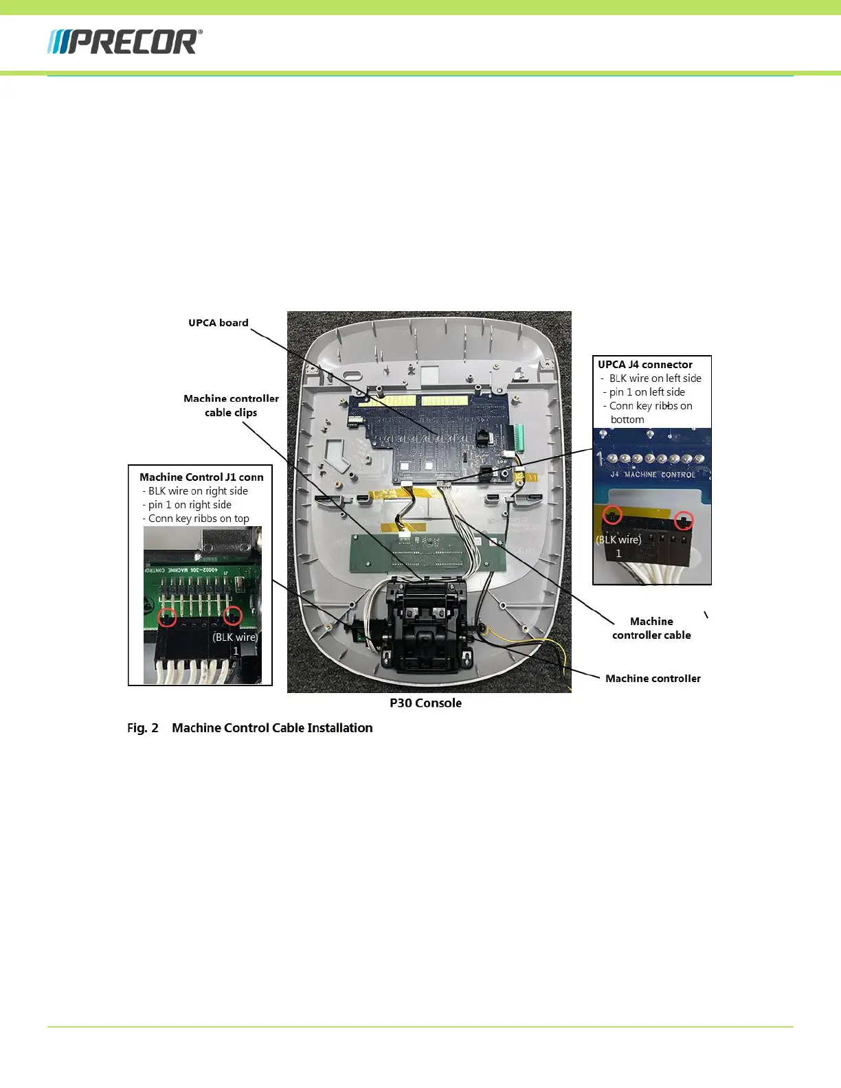
5 Connect the new machine controller cable to the UPCA - J4 MACHINE CONTROL connector making sure that the
black wire (pin 1) is located on the left side of the connector (Fig. 2).
a Position the cable connector so that the connector key ribs are on the bottom facing downward away from the
UPCA board. Also make sure that the black wire is on the left side aligned with pin 1 of the UPCA - J4 MACHINE
CONTROL connector.
b Align the 8 connector pin sockets and plug in the cable connector (Fig. 2).
6 Connect the new machine controller cable to the machine controller PCA board - J1 MACHINE CONTROL connector
making sure that the black wire (pin 1) is located on the right side of the connector (Fig. 2).
a Position the cable ribbon connector so that the connector key ribs are on the top facing upward away from the
PCA board. Also make sure that the black wire is on the right side aligned with pin 1 of the machine controller -
J1 MACHINE CONTROL connector.
b Align the 8 connector pin sockets and plug in the cable connector (Fig. 2).
7 Reinstall the console back covers. Make sure to reconnect the HR cable connector.
8 Reinstall the console onto the base unit.
9 Connect power and verify operation of the machine INCLINE and SPEED/RESISTANCE controls.
a Go to Diagnostics Hardware Validation mode and select Keyboard Test.
b Slowly move the INCLINE control approximately half way until the first INCLINE LED switches OFF, pause, and
continue movement to maximum and verify the second LED switches OFF. If the LEDs do not switch OFF there is
a problem with the machine control. Perform this test for both raise and lower incline directions.
c Repeat the Keyboard Test for the SPEED/RESISTANCE control.
d Press and hold the PAUSE key to exit Diagnostic Hardware Validation mode.
e Operate the INCLINE control through the entire range from min to max levels.
f Operate the SPEED/RESISTANCE control through the entire range from min to max value.
g Verify the HR function.
10 Verify machine operation (see service manual) and return to service.