To assemble the Spinner® Ride, follow the steps in the order listed in this assembly
guide. For more product information, visit us at www.precor.com.
WARNING At least two people are required to assemble the equipment.
DO NOT attempt assembly by yourself.
Assembly Requirements
When assembling the bike, we recommend you:
• Assemble the equipment close to where you plan to use it.
• Assemble the equipment on a solid, flat surface, so that it remains level
and stable.
• Leave a minimum of 0.5 m (19.7 in.) on at least once side of the bike
and 0.5 m (19.7 in.) behind or in front of the bike.
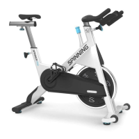
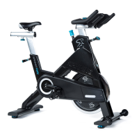
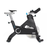
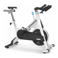
Spinner® Ride™
Assembly Guide
Hardware Kit
Begin Assembly
Remove the following parts from the packaging: handlebar assembly, hardware kit, stabilizers,
product documentation, seat assembly, and spare parts.
CAUTION Damage to the bike during assembly is not covered by the Precor Limited
Warranty.
During assembly, you must protect the handlebar and seat adjustment pop-pins
from damage.
To attach the rear stabilizer:
1. Stand the bike frame on its front end (toward flywheel) and place a piece of foam under
the bike frame (Figure 1) to protect the handlebar adjustment pop-pin from damage.
2. Attach the rear stabilizer to the frame using two bolts and two washers (Figure 2).
Using a hex key , tighten to 15.6 ft-lb (21.2 N-m).
To attach the front stabilizer:
1. Stand the bike frame on its back end and place a piece of foam under the bike frame
(Figure 3) to protect the seat adjustment pop-pin from damage.
2. Attach the front stabilizer to the frame using two bolts and two washers (Figure 4).
Using a hex key , tighten the bolts to 15.6 ft-lb (21.2 N-m).
3. Return the bike to the upright position.
Figure 2
Figure 3
Figure 4
Seat assembly
Handlebar
assembly
Rear
stabilizer
Seat post
Handlebar post
Front
stabilizer
Pedal
Seat
adjustment
pop-pin
Handlebar
adjustment
pop-pin
Seat
slider knob
Resistance
knob
Flywheel
Adjustment feet
Crank arm
Component Quantity
Socket head bolt (M8 x 30 mm) 4
Flat washer (8 mm) 4
Socket head bolt (M3 x 8 mm) 4
Socket head bolt (M8 x 16 mm) 2
Socket head flat bolt (M8 x 16 mm) 2
Socket head set screw (M8 x 16 mm) 1
Component Quantity
Seat slider end cap 1
2.5 mm hex key 1
4 mm hex key 1
5 mm hex key 1
6 mm hex key 1
8 mm hex key 1
Figure 1